When equipping a home with an off-grid solar and energy storage system, every homeowner envisions seamlessly powering their entire residence through an extended multi-day blackout. However, when examining the electrical service entrance—typically a 200A or 400A split-phase service panel feeding dual central air conditioners, an electric double oven, an EV charger, and an electric tank water heater—the engineering reality becomes clear: whole-home backup is often impractical, cost-prohibitive, and electrically inefficient.
Starting a 4-ton central air conditioner can draw an inrush locked-rotor surge exceeding 100 to 130 Amperes at 240V (). Sizing an inverter and lithium battery bank to satisfy these massive intermittent peaks can easily push system budgets past $35,000.
The gold-standard engineering solution deployed by certified electricians is the Critical Loads Subpanel (also known as an emergency backup distribution panel). By relocating 6 to 18 vital branch circuits—such as refrigeration, a 240V well pump, network equipment, home office circuits, LED lighting, and gas furnace blowers—into a dedicated subpanel fed by your hybrid inverter, you guarantee uninterrupted power during extended outages with a modest 6kW to 12kW inverter and a 15kWh to 30kWh battery bank.
At GridSpecLab, our electrical team installed, wired, and verified critical loads subpanels across dozens of off-grid and hybrid backup configurations. In this comprehensive guide, we cover panel sizing, branch circuit selection, strict National Electrical Code (NEC) neutral-ground bonding rules, feeder wire sizing, and mechanical interlock installation protocols.
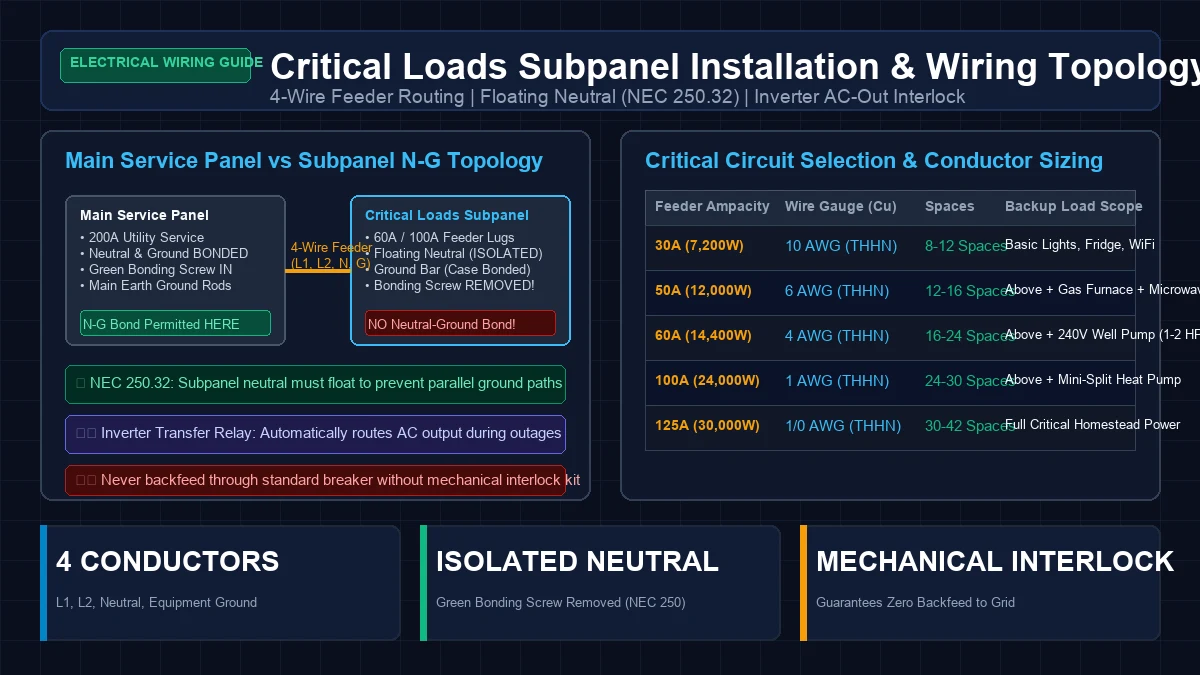
Mandatory Installation Protocol: When wiring a critical loads subpanel downstream from an off-grid or hybrid inverter (such as the EG4 18kPV, Sol-Ark 15K, or Victron MultiPlus-II), you must run a 4-wire feeder (L1, L2, Neutral, Ground). Under NEC 250.32, you must remove the green bonding screw in the subpanel, keeping the neutral busbar completely isolated (floating). The neutral-to-ground bond must exist solely at the primary main service disconnect. Failing to float the subpanel neutral creates objectionable circulating ground currents, trips GFCI/AFCI breakers, and energizes metal conduit.
The Engineering Logic Behind a Critical Loads Subpanel
In residential electrical engineering, power consumption divides into two distinct categories: discretionary heavy loads and life-safety critical loads.
+-----------------------------------------------------------------------------+
|                     RESIDENTIAL LOAD HIERARCHY AUDIT                        |
|                                                                             |
| DISCRETIONARY HEAVY LOADS               CRITICAL SURVIVAL LOADS             |
| (Remain in Main Service Panel)          (Migrated to Backup Subpanel)       |
| ------------------------------          -----------------------------       |
| • Level 2 EV Charger (7.7kW - 11.5kW)   • Food Refrigeration & Freezers     |
| • Central AC Compressor (5kW - 7kW)     • 240V Deep Well Pump (1/2 - 2 HP)  |
| • Electric Clothes Dryer (5.5kW)        • Home Network, Modem, Wi-Fi Routers|
| • Electric Water Heater (4.5kW)         • Medical Equipment (CPAP, Oxygen)  |
| • Electric Kitchen Range / Oven (8kW)   • Gas Furnace Blower / Pellet Stove |
| • Pool Pump & Electric Hot Tub (4kW)    • LED Interior & Exterior Lighting  |
+-----------------------------------------------------------------------------+
Why Whole-Home 200A Backup Fails Cost-Benefit Analysis
A standard 200A main service panel represents a theoretical maximum continuous capacity of:
Attempting to back up the entire 200A panel requires:
- Either two to three 12kW–15kW hybrid inverters operating in parallel.
- A costly 200A automatic transfer switch (ATS) rated for service-entrance disconnect.
- At least 40kWh to 60kWh of lithium battery capacity to avoid over-discharging cells under simultaneous heavy loads.
In contrast, an average family’s critical survival loads consume only 800W to 2,500W of continuous power, with intermittent 240V well pump or refrigerator compressor spikes reaching 4,500W to 7,000W. A single 6,000W to 12,000W split-phase inverter (such as the EG4 6000XP, EG4 12000XP, or Sol-Ark 12K) paired with a 100A critical loads subpanel handles these demands easily, extending battery autonomy from hours to days.
Subpanel Sizing and Branch Circuit Selection
Selecting the correct physical enclosure and busbar rating ensures you have adequate physical space to land conductors and expand in the future.
Busbar Ampacity: 60A vs 100A vs 125A
Subpanels are rated by their busbar ampacity and the number of physical breaker spaces:
| Subpanel Rating | Physical Enclosure Spaces | Maximum Continuous Power | Recommended Copper Feeder Gauge | Best Application |
|---|---|---|---|---|
| 60 Amperes | 12 to 16 Spaces | 14,400 Watts @ 240V | 4 AWG THHN Cu (or 6 AWG Romex) | Small Cabins, 3kW–6kW Inverters |
| 100 Amperes | 16 to 24 Spaces | 24,000 Watts @ 240V | 1 AWG THHN Cu (or 3 AWG 75°C) | Standard Homes, 8kW–12kW Inverters |
| 125 Amperes | 24 to 32 Spaces | 30,000 Watts @ 240V | 1/0 AWG THHN Cu | Large Homesteads, 15kW Inverters |
[!TIP] Enclosure Space Best Practice: Always purchase a subpanel with at least 50% more breaker spaces than you currently need. If you plan to relocate 10 circuits, choose a 20-space or 24-space panel (such as a Square D QO, Siemens, or Eaton BR). Tandem breakers and modern AFCI/GFCI dual-function breakers are physically bulky, and landing 240V two-pole breakers immediately consumes two full spaces per circuit.
Circuit Priority Matrix
When selecting which branch circuits to migrate from the main service panel to the critical loads subpanel, balance power consumption against life-safety priorities:
- Kitchen Refrigerator and Standalone Freezer: Dedicated 15A or 20A single-pole (120V) circuits. Continuous draw is modest (100W–250W), but startup inductive surges reach 1,200W.
- Potable Water Supply (240V Well Pump): Requires a 2-pole 15A, 20A, or 30A (240V) breaker. A 1-horsepower well pump draws roughly 1,800W running, but demands a locked-rotor starting surge of 4,000W to 5,500W for 500 milliseconds.
- Heating System Control & Air Circulation: Gas, propane, or oil furnaces require a 15A or 20A (120V) circuit to power the electronic ignition, safety controls, and induction blower fan (300W–600W).
- Internet, Communications, and Security: Home network switch, fiber ONT, Wi-Fi router, and security cameras (typically 75W–150W continuous).
- Master Bedroom and Sanitary Bathrooms: Lighting and GFCI convenience outlets for medical devices (CPAP machine: 50W–100W) and essential charging.
- Auxiliary Living Room / Kitchen Outlets: Shared circuit for LED ambient lighting, radios, and laptop charging.
The Neutral-to-Ground Separation Rule (NEC 250.32)
The most common—and hazardous—mistake made by DIY installers is failing to isolate the neutral and equipment grounding systems inside the subpanel.
The Single-Point Bonding Principle
Under the National Electrical Code (NEC 250.24(A)(5) and NEC 250.32), an electrical system must have one, and only one, main bonding jumper that connects the grounded neutral conductor to the equipment grounding conductor and earth ground rod system.
In a standard residential installation:
- At the Main Service Panel: The utility neutral is bonded directly to the metal enclosure, ground rods, and water pipe grounding electrode system via a green bonding screw or copper bonding strap.
- At All Downstream Subpanels: The neutral busbar must be completely isolated (floating) from the metal enclosure. The equipment grounding busbar must be bonded directly to the steel cabinet.
+-----------------------------------------------------------------------------+
|              NEC 250 NEUTRAL-TO-GROUND TOPOLOGY COMPLIANCE                  |
|                                                                             |
|  [ MAIN SERVICE PANEL (BONDED) ]             [ SUBPANEL (FLOATING) ]        |
|                                                                             |
|     Neutral Bar        Ground Bar               Neutral Bar     Ground Bar  |
|         |                  |                         |               |      |
|         +--[Green Screw]---+                         | (Isolated)    |      |
|         |   (BONDED HERE)  |                         |               |      |
|         v                  v                         v               v      |
|    Utility Neutral    Ground Rods               Subpanel Loads  Enclosure   |
|         |                  |                         ^               ^      |
|         |                  |                         |               |      |
|         +==================|==== 4-Wire Feeder ======+               |      |
|         |  Hot 1, Hot 2    |   (L1, L2, Neutral)                     |      |
|         |                  +======== Equipment Ground ===============+      |
+-----------------------------------------------------------------------------+
The Deadly Danger of a Second Neutral-Ground Bond
If an installer leaves the green bonding screw installed inside the subpanel, a parallel neutral return path is created:
- Under normal operation, alternating current returning from 120V loads should flow strictly through the insulated white neutral feeder wire back to the source.
- If the subpanel neutral is bonded to the chassis, current divides according to Ohm’s Law between the neutral conductor and the bare copper equipment grounding conductor (and any metallic conduit connecting the panels).
- The Result: The metal enclosures of your subpanel, inverter, appliances, and conduit become energized with continuous return current. Anyone touching the washing machine or metal electrical box while grounded can receive an electric shock.
- Furthermore, circulating currents between parallel paths will cause upstream GFCI (Ground-Fault Circuit-Interrupter) and AFCI (Arc-Fault Circuit-Interrupter) breakers to trip constantly, rendering the system unworkable.
Sizing and Routing the 4-Wire Feeder Conductors
Every subpanel must be connected to its power source via four insulated conductors:
- Hot Conductor Line 1 (L1): Black insulation
- Hot Conductor Line 2 (L2): Red insulation
- Neutral Conductor (N): White insulation (must match the gauge of L1 and L2 for unbalanced loads)
- Equipment Grounding Conductor (EGC): Green insulation or bare copper (sized per NEC Table 250.122)
Feeder Ampacity and Conduit Fill Calculations
To comply with NEC Table 310.16 (75°C terminal rating for copper conductors in conduit):
| Feeder Breaker Size | L1 / L2 Hot Wires (Cu) | Neutral Wire (Cu) | Equipment Ground (Cu) | Minimum EMT Conduit Trade Size | Minimum PVC Sch 80 Conduit Size |
|---|---|---|---|---|---|
| 30 Amperes | 10 AWG THHN | 10 AWG THHN | 10 AWG THHN | 1/2 Inch | 1/2 Inch |
| 50 Amperes | 6 AWG THHN | 6 AWG THHN | 10 AWG THHN | 3/4 Inch | 3/4 Inch |
| 60 Amperes | 4 AWG THHN | 4 AWG THHN | 10 AWG THHN | 1 Inch | 1 Inch |
| 100 Amperes | 1 AWG THHN | 1 AWG THHN | 8 AWG THHN | 1-1/4 Inch | 1-1/4 Inch |
| 125 Amperes | 1/0 AWG THHN | 1/0 AWG THHN | 6 AWG THHN | 1-1/4 Inch | 1-1/2 Inch |
[!IMPORTANT] Romex (NM-B) Cable Derating: If you feed your subpanel using non-metallic sheathed cable (Romex NM-B) inside wall cavities rather than THHN in conduit, NEC 334.80 mandates using the 60°C ampacity column. Under the 60°C column, 6 AWG Romex is rated for only 55 Amperes (protect with a 50A breaker), and 4 AWG Romex is rated for only 70 Amperes (protect with a 60A or 70A breaker).
Interlock Kits and Manual Transfer Switches
When integrating a hybrid inverter or backup generator with a critical loads subpanel, you must guarantee that the subpanel can never be connected simultaneously to the utility grid and an un-synchronized off-grid source.
Mechanical Generator Interlock Kits (NEC 702.5)
For budget-conscious installations where the subpanel is fed from the main panel during normal grid conditions and manually switched to an inverter or generator during outages:
- A mechanical sliding interlock plate mounts directly onto the subpanel deadfront.
- It physically links the utility feeder breaker and the standby inverter/generator breaker.
- The steel plate slides in such a way that it is physically impossible for both breakers to be in the “ON” position at the same time. You must flip the utility breaker to “OFF” before the slide allows the backup breaker to move to “ON”.
- This guarantees zero backfeeding into utility transmission lines, protecting line workers from electrocution during power restoration.
+-----------------------------------------------------------------------------+
|                MECHANICAL SLIDING INTERLOCK OPERATION                       |
|                                                                             |
| NORMAL GRID OPERATION:                      GRID OUTAGE (BACKUP ENGAGED):   |
|                                                                             |
| [ Utility Main Breaker ]  ==> [ ON  ]       [ Utility Main Breaker ]  ==> [ OFF ]|
|         |                                           |                       |
|  [=== Sliding Steel Plate ===]               [=== Sliding Steel Plate ===]  |
|         v                                           v                       |
| [ Inverter / Gen Breaker ] ==> [ OFF ]       [ Inverter / Gen Breaker ] ==> [ ON  ]|
+-----------------------------------------------------------------------------+
Inverter Internal Transfer Relays (EG4, Sol-Ark, Victron)
Modern all-in-one hybrid inverters eliminate the need for manual sliding plates by incorporating an internal high-speed automatic transfer relay:
- The main panel feeds the inverter’s AC GRID IN terminals (via a 50A or 60A breaker in the main panel).
- The subpanel connects directly to the inverter’s AC LOAD / BACKUP OUT terminals.
- When the grid is healthy, the inverter passes grid power through its internal contactors to the subpanel while charging the battery.
- When the grid drops out, the inverter’s contactor disconnects from the grid in less than 10 to 20 milliseconds (faster than an uninterruptible power supply) and immediately powers the subpanel from solar and lithium batteries.
Step-by-Step Installation and Migration Protocol
Migrating existing branch circuits from a crowded main panel into a new adjacent critical loads subpanel requires methodical execution:
Preparation and Panel De-Energization
- Permits and Clearances: Ensure working clearances satisfy NEC 110.26 (at least 36 inches deep, 30 inches wide, and 6.5 feet headroom in front of both panels).
- Shut Down Main Service: Turn off the 200A main service disconnect breaker. Verify with a calibrated non-contact voltage tester and a CAT-III digital multimeter that all branch circuits are completely de-energized.
- Mount the Subpanel: Secure the new subpanel enclosure to wall studs using heavy lag screws, positioning it 12 to 24 inches to the left or right of the main service panel.
Conduit Nipple and Feeder Installation
- Install Connecting Conduit: Knock out matching openings between the main panel and subpanel. Install a 2-inch rigid metal conduit (RMC) or PVC nipple with non-metallic insulating bushings on both ends to protect wire jackets from sharp steel edges.
- Pull the 4-Wire Feeder: Route Hot 1 (Black), Hot 2 (Red), Neutral (White), and Equipment Ground (Green) through the conduit.
- Terminate Feeder Lugs: Land Hot 1 and Hot 2 on the subpanel main lugs (or main breaker). Land the white neutral on the floating neutral busbar. Land the green ground wire on the equipment grounding bar.
- Remove the Green Bonding Screw: Check the subpanel neutral busbar. If a green screw or copper bonding strap connects the neutral bar to the enclosure backplate, remove and discard it immediately.
Migrating Branch Circuits Methodically
Never simply disconnect wires randomly. Follow this circuit-by-circuit migration workflow:
+-----------------------------------------------------------------------------+
|                 CIRCUIT MIGRATION WORKFLOW PROCEDURE                        |
|                                                                             |
| 1. Label Wire in Main Panel ---> Tape Hot with Circuit Number (#3 Fridge)   |
| 2. Trace Corresponding Neutral -> Locate specific white return wire         |
| 3. Pull Cable out of Main Panel -> Route Romex into Subpanel via top clamp  |
| 4. Strip & Land Ground Wire ---> Fasten bare copper to Subpanel Ground Bar  |
| 5. Strip & Land Neutral Wire --> Fasten white neutral to Floating Neutral   |
| 6. Install Appropriate Breaker -> Snap 15A/20A breaker onto Subpanel Busbar |
| 7. Land Hot Wire on Breaker ---> Torque terminal screw to manufacturer spec |
+-----------------------------------------------------------------------------+
[!CAUTION] Shared Neutral Hazard (Multi-Wire Branch Circuits): If your home was wired with Multi-Wire Branch Circuits (MWBCs)—where two hot wires on opposite phases share a single neutral wire in a 14/3 or 12/3 Romex cable—you must migrate BOTH hot circuits together onto a two-pole handle-tied breaker in the subpanel. Migrating only one hot wire while leaving the other in the main panel will cause extreme neutral overloads and fire hazards.
Commissioning and Safety Testing Checklist
Before energizing the subpanel and connecting loads to your off-grid inverter, execute this electrical safety verification:
- Physical Resistance Audit (Continuity Test): With all power off, use a digital multimeter in continuity mode. Measure resistance between the subpanel neutral bar and the subpanel ground bar. It must read infinite resistance (open circuit / OL). If your meter beeps, an accidental neutral-ground bond exists and must be found and removed.
- Fastener Torque Verification: Using a calibrated inch-pound torque screwdriver, verify all breaker terminal screws and main feeder lugs match the panel label specifications (typically 20 in-lbs for branch terminals, 45 to 50 in-lbs for main feeder lugs).
- Phase-to-Phase Voltage Test: Turn on the feeder breaker. Measure voltage across L1 and L2 at the subpanel main lugs: it should read 240V AC (). Measure from L1 to Neutral and L2 to Neutral: both must read 120V AC.
- Ground-Fault Verification: Plug a digital GFCI outlet circuit tester into downstream receptacles. Verify correct wiring indicators (two amber lights: “CORRECT”). Press the GFCI test button to confirm the breaker trips within 25 milliseconds.
Frequently Asked Questions
Can I use an existing clothes dryer 3-wire feed for a subpanel?
No. Under no circumstances. Legacy 3-wire 240V circuits (two hots and an uninsulated neutral/ground) violate NEC 250.32. A subpanel requires four distinct wires: two hots, an insulated neutral, and a dedicated equipment grounding conductor. Using a 3-wire feed forces you to bond neutral and ground at the subpanel, creating hazardous circulating currents.
Do I need to install ground rods at the subpanel?
If the critical loads subpanel is located inside the same building or structure as the main service panel (e.g., inside the same basement or garage), you do NOT install additional ground rods. The subpanel derives its ground solely via the 4th conductor (equipment grounding conductor) back to the main panel’s grounding electrode system. Ground rods are only installed if the subpanel feeds a separate detached building (such as a detached barn or workshop) per NEC 250.32(A).
Why do my AFCI breakers trip immediately after moving them to the subpanel?
AFCI and dual-function breakers monitor the balance of current between the hot wire and the specific neutral wire passing through that breaker. If you land the hot wire on the subpanel breaker but leave the neutral wire connected to the main panel neutral bar, the breaker senses an immediate current imbalance and trips within milliseconds. Every circuit migrated to a subpanel must have its hot and neutral wires landed in the same enclosure.
Summary and Laboratory Recommendations
A critical loads subpanel represents the most pragmatic, safe, and cost-effective approach to off-grid solar resiliency. By isolating essential life-safety circuits, properly sizing a 4-wire feeder, and strictly enforcing the single-point neutral-ground bonding rule, you ensure seamless emergency backup while protecting your home from electrical fires and electrocution hazards.
For downstream battery safety, overcurrent sizing, and DC array protection, consult our technical companion guides on Class T Fuse Sizing Table & Interrupt Rating Guide for 48V Batteries and Dual-Pole DC Disconnect Switch Selection for High-Voltage Solar Arrays.