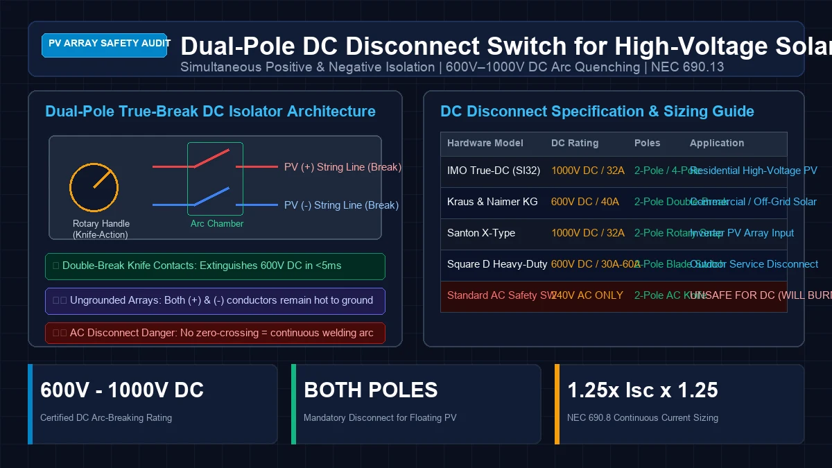
When designing a grid-tied or hybrid solar energy system operating high-voltage photovoltaic strings, the DC disconnect switch represents the first line of defense for emergency first responders, maintenance technicians, and system hardware. Yet, across DIY off-grid builds and commercial installations alike, DC switchgear is among the most frequently misunderstood and dangerously misapplied components in the solar industry.
A high-voltage solar array behaves completely differently from residential AC grid power. An AC circuit operating at 120V or 240V alternates direction 60 times per second, passing through zero volts twice every cycle (120 zero-crossings per second). When an AC switch opens, this natural voltage zero allows the resulting electric spark to collapse and extinguish on its own.
In a 300V to 600V direct-current solar circuit, voltage remains completely constant under sunlight. If an unrated switch attempts to break 15 to 30 Amperes of DC current, the electric arc acts like a continuous plasma cutting torch. The arc will ionize the surrounding air, melt brass terminals, vaporize plastic enclosures, and ignite structure fires before the contacts ever separate far enough to extinguish the flame.
At GridSpecLab, our electrical engineers evaluated the mechanical architectures, arc-quenching chambers, and thermal performance of high-voltage DC disconnect switches. In this technical guide, we break down DC arc physics, explain why dual-pole isolation is mandatory on modern ungrounded arrays, provide temperature-corrected sizing formulas, and outline compliance with National Electrical Code (NEC) Sections 690.13 and 690.15.
Mandatory Requirement: Every solar PV string operating above 50V DC must pass through a UL 98B-listed, load-break rated, dual-pole DC disconnect switch installed within sight of the inverter. Modern transformerless inverters operate ungrounded floating arrays, making dual-pole isolation (breaking both positive and negative conductors simultaneously) legally required. Using standard AC disconnect switches or air conditioning pullouts on DC circuits creates catastrophic arc-flash fire hazards and violates electrical code.
High-Voltage Direct Current Arc Physics
To understand why a dedicated DC disconnect switch is non-negotiable, you must examine the electro-physics of electric arcs under direct current.
The Mechanism of Continuous DC Arcing
When two energized electrical contacts begin to separate while current is flowing, the contact surface area shrinks to microscopic contact points right before physical detachment. The localized current density spikes dramatically, heating the metal past its boiling point and boiling off metal atoms.
This vaporized metal forms an ionized plasma channel between the separating contacts. The power dissipated inside the arc is:
In an alternating current circuit, the voltage collapses to zero volts every 8.3 milliseconds (at 60Hz). When , the power feeding the plasma channel drops to zero, allowing the ionized gas to cool, deionize, and extinguish before the voltage rises in the reverse polarity.
In direct current, the driving potential remains steady at 300V, 450V, or 600V DC. Because there are no zero-crossings, the electric arc will continue burning across air gaps of several inches. An established 500V DC arc easily burns at temperatures between 5,500°F and 9,000°F—hot enough to instantly liquify copper (melting point 1,984°F) and vaporize steel.
+-----------------------------------------------------------------------------+
|                 AC VS DC CONTACT OPENING BEHAVIOR COMPARISON                |
|                                                                             |
| 240V AC Contact Separation:                                                 |
| Contact Opens ---> Spark Forms ---> Zero Crossing at 8.3ms ---> ARC QUENCHED |
|                                                                             |
| 500V DC Contact Separation (Standard AC Switch):                            |
| Contact Opens ---> Spark Forms ---> NO ZERO CROSSING ---> SUSTAINED PLASMA  |
|               ---> Metal Vaporizes ---> Terminal Melts ---> CABINET FIRE    |
|                                                                             |
| 500V DC True-DC Switch (Rotary Knife + Arc Chute):                          |
| Snap Mechanism (under 5ms) ---> Double-Break Gap ---> Magnetic Arc Chute Quench  |
+-----------------------------------------------------------------------------+
Mechanical Solutions: Double-Break Contacts and Magnetic Blowouts
Dedicated DC disconnect switches (such as the IMO SI32 or Kraus & Naimer KG series) utilize three mechanical innovations to reliably extinguish DC arcs under full load:
- Operator-Independent Snap Action: In a cheap household switch, moving the physical handle slowly causes the internal contacts to separate slowly. In a true DC switch, the handle winds an internal torsion spring. Once the handle reaches a critical trigger angle, the spring releases stored kinetic energy, snapping the contacts open at over 5 meters per second in less than 5 milliseconds, completely independent of how hesitantly an operator moves the lever.
- Double-Break Knife Contacts: Rather than breaking the conductor at a single physical point, a rotary DC switch utilizes a bridge contact that opens two gaps in series per pole simultaneously. Breaking the circuit across two points cuts the arc voltage requirement in half, requiring twice as much energy to sustain the plasma.
- Magnetic Arc Blowouts and Deionizing Chutes: High-voltage DC switchgear incorporates permanent magnets situated adjacent to the contact gap. The magnetic field exerts a Lorentz force on the moving electrons inside the arc, physically bending and stretching the plasma column into metal splitter plates (deionizing arc chutes) that cool and extinguish the arc within milliseconds.
Why Dual-Pole Disconnects Are Mandatory on Ungrounded Arrays
A common source of confusion among solar installers with traditional AC electrical backgrounds is whether a DC disconnect needs to interrupt both conductors (positive and negative) or only the positive conductor.
Grounded Systems (Legacy Technology)
Prior to 2012, most residential solar systems utilized central inverters with internal isolation transformers. In these legacy setups, the negative DC conductor was bonded directly to earth ground at the inverter. Because the negative wire was held at zero volts relative to ground, interrupting only the positive conductor was sufficient to de-energize the circuit.
Modern Transformerless Inverters and Floating Arrays
Over 95% of modern grid-tied and hybrid inverters (including EG4 18kPV, EG4 6000XP, Sol-Ark 12K/15K, SMA Sunny Boy, Fronius Primo, and Enphase systems) utilize transformerless (non-isolated) topology.
In a transformerless inverter:
- Neither the positive nor the negative PV conductor is connected to ground. The entire array is an ungrounded, floating DC circuit.
- The AC utility neutral is referenced to ground on the grid side. Through the inverter’s internal H-bridge semiconductor switches, an AC common-mode voltage is superimposed onto the DC array conductors.
- Both the positive (+) and negative (-) conductors carry lethal voltages relative to earth ground. For example, on a 400V DC string, the positive wire may sit at to ground while the negative wire sits at to ground.
If an installer uses a single-pole switch that disconnects only the positive wire, the negative conductor remains fully energized relative to earth ground. If a firefighter, service technician, or homeowner contacts the negative wire while grounded, they complete a lethal electrical circuit through their body.
Under NEC 690.13(F), all ungrounded DC conductors originating from a photovoltaic array must have a disconnect that opens all ungrounded conductors simultaneously. On a floating PV string, this mandates a dual-pole (2-pole) disconnect switch.
Sizing Calculations for Voltage and Current
Selecting an undersized DC disconnect switch will result in contact overheating, switch body degradation, and catastrophic failure when opening during array ground faults. You must calculate both maximum open-circuit voltage () and continuous operating current ().
Maximum Voltage with Freezing Temperature Correction
Photovoltaic solar panels produce higher voltages as temperatures drop. The rated open-circuit voltage () listed on a module datasheet is measured at Standard Test Conditions (STC: 25°C / 77°F). In winter, when ambient temperatures drop to freezing, array voltage rises significantly.
Under NEC 690.7, the maximum photovoltaic system voltage () must be calculated using the module manufacturer’s open-circuit voltage temperature coefficient () at the historic lowest recorded ambient temperature for the installation site:
Where:
- = Rated open-circuit voltage per module at 25°C
- = Temperature coefficient of (typically negative, e.g., or )
- = Extreme annual low design temperature for the installation location
- = Number of solar modules connected in series per string
Example Engineering Calculation:
Consider a string of 10 modern 450W solar panels:
- Installation Site Low Temperature: ()
- Temperature Delta:
- Voltage Rise Factor: (11.2% increase)
- Single Module Cold :
- Total String :
In this example, an unrated 240V switch or budget 400V disconnect would experience dielectric breakdown. The installation requires a switch rated for at least 600V DC.
Minimum Current Sizing (The 156% Rule)
Solar panels do not operate as rigid voltage sources; they operate as current-limited devices. Under conditions of high solar irradiance, cloud lensing, and snow reflection (albedo), solar panels can produce current well in excess of their STC short-circuit current ().
NEC 690.8 mandates a two-tier safety factor for DC disconnect and conductor sizing:
- Solar Irradiance Multiplier (125%): Factor for peak irradiance exceeding 1,000 W/m²:
- Continuous Duty Multiplier (125%): Because solar power generation runs continuously for more than 3 hours:
Combining these two factors yields the mandatory 156% multiplier (1.56x):
For a high-efficiency module with an of 14.2 Amperes:
A 16A or 20A switch would be undersized and fail thermal testing; the installation mandates a minimum 25A or 32A rated DC switch.
Hardware Comparison: Rotary DC Isolators vs Molded Case Breakers
When specifying hardware for residential and commercial solar arrays, three distinct categories of disconnects are encountered:
| Hardware Category | Typical DC Voltage Rating | Contact Mechanism | Enclosure Rating | Load-Break Certified? | Suitability for PV Arrays |
|---|---|---|---|---|---|
| Rotary True-DC Isolator (IMO SI32, Kraus & Naimer) | 600V – 1,000V DC | Double-break rotary knife with spring snap | NEMA 4X / IP66 UV-resistant | Yes (UL 98B & IEC 60947-3) | Gold Standard for String Isolation |
| Molded Case DC Circuit Breaker (MCCB) | 500V – 1,000V DC | Mechanical trip lever with magnetic arc chute | NEMA 3R steel cabinet | Yes (UL 489B) | Best for Multi-String Combiners |
| Standard AC Safety Switch (Square D / Eaton AC) | 240V AC (Unrated DC) | Slow-break single knife blade | NEMA 3R | No (AC Only) | PROHIBITED (Will ignite fire on DC) |
| Air Conditioner Pull-Out Disconnect | 240V AC (Unrated DC) | Manual copper pullout bar | Plastic NEMA 3R | No | LETHAL (Explosive arc hazard) |
+-----------------------------------------------------------------------------+
|                IMO TRUE-DC (SI32) ROTARY SWITCH SCHEMATIC                   |
|                                                                             |
|            [ PV Array (+) String ]     [ PV Array (-) String ]              |
|                      |                           |                          |
|                      v                           v                          |
|             +-----------------+         +-----------------+                 |
|             |  Pole 1 (Knife) |         |  Pole 2 (Knife) |                 |
|             |  Double-Break   |         |  Double-Break   |                 |
|             |   Arc Chute     |         |   Arc Chute     |                 |
|             +-----------------+         +-----------------+                 |
|                      |                           |                          |
|                      +-------------+-------------+                          |
|                                    |                                        |
|                          [ Heavy Torsion Spring ]                           |
|                                    |                                        |
|                         [ External Rotary Handle ]                          |
|                                                                             |
|                      v                           v                          |
|             [ Inverter PV (+) ]         [ Inverter PV (-) ]                 |
+-----------------------------------------------------------------------------+
Why Rotary DC Isolators Are the Preferred Industry Standard
Rotary DC switches (such as the IMO SI32 series) have become the global standard for string inverters for several engineering reasons:
- Compact Footprint: Unlike massive steel safety switch enclosures, rotary isolators are housed in compact, UV-stabilized polycarbonate enclosures that mount directly adjacent to the inverter.
- Four-Pole Series Configurations: Many rotary isolators feature four separate contacts that can be wired in series (two poles in series for positive, two poles in series for negative). This quadruples the arc air gap, allowing a compact switch to safely interrupt up to 1,000V DC at 32 Amps.
- Lockable in the OFF Position: Incorporates an integrated padlock hasp that accepts standard OSHA lockout/tagout (LOTO) padlocks, ensuring safety during panel cleaning, roof maintenance, or inverter replacement.
NEC Compliance Checklist: Articles 690.13 and 690.15
To pass municipal electrical inspection and satisfy utility interconnection requirements, your DC disconnect installation must strictly comply with the following National Electrical Code standards:
Location and Accessibility Requirements (NEC 690.13)
The PV system disconnecting means must be installed in a readily accessible location. It cannot be mounted behind locked doors, inside residential living spaces, or in locations requiring portable ladders to access.
Grouping and Line-of-Sight Placement (NEC 690.15)
The DC disconnect switch must be located within sight of the inverter (within 50 feet and unobstructed). If the inverter is installed indoors (e.g., in a basement or garage) and the solar conductors enter from outdoors, an external DC disconnect must be provided at the building penetration point so utility workers can de-energize the DC conductors before entering the building.
Certified Load-Break Rating Standard (NEC 690.13)
The disconnect must be certified as a load-break switch. A disconnect rated “Do Not Open Under Load” is legally unacceptable as the primary PV system disconnect; it must be capable of safely interrupting full prospective fault current under full solar generation.
Simultaneous Conductor Interruption (NEC 690.13)
The switch must simultaneously disconnect all ungrounded conductors of the DC circuit. For ungrounded floating arrays, both the positive and negative conductors must pass through the switch poles.
Warning Labels and Identification Placards (NEC 690.13)
The switch must be permanently marked with an engraved, UV-resistant phenolic placard stating:
- “PHOTOVOLTAIC SYSTEM DC DISCONNECT”
- Maximum Photovoltaic System Voltage ()
- Maximum Rated Short-Circuit Current ()
- Nominal Operating Voltage and Current
Common DIY Installation Mistakes and Failure Modes
During field audits of DIY and budget solar installations, our testing team regularly identifies four critical DC disconnect installation errors:
Using Reverse Polarity on Polarized DC Breakers
Some molded case DC circuit breakers are polarized, meaning they utilize permanent blowout magnets that rely on current flowing in a specific direction to push the arc into the cooling plates. If an installer wires a polarized breaker backwards (e.g., connecting the array to the load terminals), the magnetic field pulls the arc away from the cooling chute and into the operating mechanism, destroying the breaker during a trip. Always verify if a DC breaker is marked with + and - polarity indicators, or utilize non-polarized rotary isolators (such as IMO True-DC) which are completely bidirectional.
Daisy-Chaining Inadequate Wire Gauges
Sizing the disconnect switch properly is useless if the connecting conductors are undersized. The wire connecting the array to the disconnect and from the disconnect to the inverter must be pure copper rated for 90°C (such as UL 4703 PV wire or THHN copper), sized according to the 156% continuous duty rule with ambient temperature derating applied.
Omission of Weatherproof Cable Glands
Rotary DC switches mounted outdoors require NEMA 4X (IP66) water resistance. Installers who drill holes in the top of the switch enclosure create immediate water ingress points. Always enter the enclosure from the bottom, using certified IP68 liquid-tight cable glands or UV-resistant watertight conduit fittings with silicone O-rings.
Failing to Torque Stud Terminals
Under continuous DC currents of 15A to 30A, loose terminal screws create high contact resistance. This localized resistance generates thermal hotspots that melt the plastic terminal block and trigger nuisance thermal faults. Always tighten terminal screws with a calibrated torque screwdriver to the manufacturer’s exact specification (typically 15 to 20 in-lbs for rotary switch terminals).
Frequently Asked Questions
Can I use the built-in DC rotary switch on my inverter instead of an external disconnect?
Most modern hybrid inverters (e.g., EG4 18kPV, Sol-Ark 15K, Growatt SPF series) include an integrated rotary DC disconnect on the inverter chassis. In many jurisdictions, this integrated switch satisfies the local code requirement for an inverter disconnect. However, if the inverter is located indoors or more than 10 feet from the point of building penetration, local utilities and fire codes (NEC 690.13) frequently require a separate, lockable external DC disconnect mounted on the exterior wall of the home.
Do microinverter systems require a DC disconnect switch?
No. In an AC microinverter system (such as Enphase IQ8), each solar panel connects directly to a microinverter mounted underneath the panel on the roof. The DC run is only a few feet long and never combines into a high-voltage string. Microinverter systems operate entirely as AC circuits downstream from the roof, requiring AC disconnects and AC combiner panels rather than high-voltage DC switchgear.
What is the difference between an isolator switch and a circuit breaker?
An isolator switch (such as the IMO SI32) is designed primarily to provide safe, manual mechanical disconnection under load; it does not automatically trip during modest overloads. A DC circuit breaker combines manual disconnection with thermal and magnetic trip mechanisms that automatically open the circuit during overcurrent or short circuits. In single-string PV arrays, where the panel short-circuit current cannot exceed conductor ampacity, a rotary DC isolator is typically sufficient and preferred.
Summary and Practical Checklist
Operating a high-voltage solar array without a certified, load-break rated dual-pole DC disconnect is playing Russian roulette with electric arc flash. By selecting an authentic UL 98B-listed rotary DC switch rated for at least 600V DC and 32A, you protect your inverter, satisfy National Electrical Code mandates, and ensure the safety of your home and emergency first responders.
For detailed guidelines on downstream overcurrent protection and inverter battery interconnects, review our engineering guides on Class T Fuse Sizing Table & Interrupt Rating Guide for 48V Batteries and 4/0 AWG vs 2/0 AWG Battery Cable Sizing for 48V Inverters.