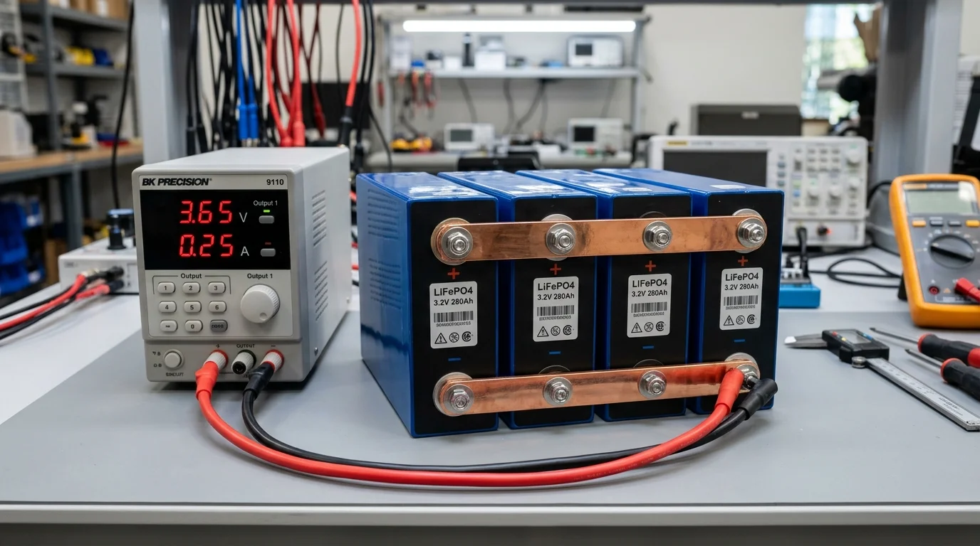
When receiving a fresh crate of Grade A prismatic lithium iron phosphate cells—such as EVE 280Ah, 304Ah, or 314Ah units—the single most critical commissioning task is top balancing.
New cells leave the manufacturing facility at roughly 30% to 50% State of Charge (SoC) for safe transit. While their resting open-circuit voltages may appear virtually identical around 3.28V to 3.29V, their individual states of charge can diverge by 5% to 15%. If you wire these cells directly into a 16S 48V series pack without top balancing, the first cell to hit 3.65V (the “runner cell”) will trip your BMS high-voltage disconnect while the remaining cells are barely at 85% capacity.
Attempting to balance a large 280Ah+ pack purely with a 50mA passive BMS can take months of frustrating false-alarm inverter shutdowns.
In this comprehensive laboratory guide, we walk you through the industry-standard Two-Stage Top Balancing Protocol. We cover equipment selection, wire sizing, precision power supply calibration, tail-current cutoff math, and the chemical physics of voltage settling.
Do not attempt to top balance a 16-cell 48V pack from empty purely in parallel using a tiny 10A power supply—it will take over 500 hours (3 weeks) of continuous running. Use the Two-Stage Method: pre-charge the pack in series with a BMS up to 3.40V per cell, then reconfigure into parallel for the final precision soak to 3.650V.
Why Top Balancing Is Non-Negotiable
The open-circuit voltage curve of LiFePO4 chemistry is notoriously flat between 15% and 85% SoC. At 3.29V, a cell could be at 30% capacity or 70% capacity—voltage alone cannot tell you.
However, once cell voltage passes 3.45V, the curve enters a steep, near-vertical knee:
Premature BMS High-Voltage Trip
In an un-balanced 16S bank, the highest cell hits 3.65V while other cells lag at 3.38V. The BMS immediately disconnects the charger to prevent cell damage.
Result: You lose 15%–25% of your bank’s total usable kWh capacity.Synchronous 100% Saturation
All 16 cells cross the upper knee together. Every cell reaches 3.65V simultaneously, allowing your inverter charger to absorb full nameplate capacity without tripping BMS alarms.
Result: Full 100% usable capacity and zero false fault trips.Required Equipment and Bench Preparation
Before beginning, assemble high-quality testing gear. Inaccurate meters or flimsy wiring will ruin balancing results.
| Essential Equipment | Recommended Specification | Purpose |
|---|---|---|
| Bench Power Supply | Adjustable CC/CV 0–30V, 10A or 20A | Delivers precision constant current and constant voltage. |
| Digital Multimeter (DMM) | 4.5-digit or 5-digit resolution (Fluke 87V or similar) | Calibrating the power supply and measuring cell terminal voltage. |
| Copper Busbars & Wiring | Laminated copper busbars + 8 AWG or 6 AWG leads | Minimizes line resistance between cells during parallel soaking. |
| Torque Wrench | Calibrated in inch-lbs or Newton-meters (3.5–5.0 Nm) | Prevents stripping aluminum terminal threads or under-torquing studs. |
| Cell Compression Fixture | Mechanical spring fixture (300 kgf / 12 psi) | Prevents cell swelling during full charge (see our Compression Guide). |
| Alcohol Prep Pads | 99% Isopropyl alcohol | Cleans oxidation and anti-corrosion oils off copper terminal pads. |
The Two-Stage Top Balancing Protocol
The biggest mistake novices make is connecting sixteen 280Ah cells in parallel at 3.29V and trying to charge 4,480Ah of storage with a 10A benchtop supply:
Instead, professional battery builders use the Two-Stage Protocol:
Charge to 3.40V per Cell (54.4V Total)
Assemble cells in 16S series with your JK BMS or Overkill Solar BMS fully connected for protection. Use your solar inverter charger or high-power 48V charger at 30A–50A.
- Charges 90% of pack energy in 4 to 6 hours
- BMS protects against any single cell overshooting
- Stop when the first cell crosses 3.450V
Soak to 3.650V CC/CV
Disassemble series busbars. Reconfigure all 16 cells in parallel (all positives together, all negatives together). Connect your calibrated bench power supply set to exactly 3.650V.
- Because cells are already at 90% SoC, soak takes only 12–18 hours
- Current gradually decays from 10A/20A down toward zero
- Disconnect when current drops below tail threshold
Step-by-Step Execution: Calibrating and Soaking
Mechanical Compression and Terminal Prep
Before running any current through the cells:
- Place cells inside your mechanical compression fixture with 0.5mm FR4 fiberglass sheets between every cell.
- Tighten spring fixtures to apply 300 kgf (12 PSI). Uncompressed cells will swell under full charge!
- Clean the aluminum terminal pads with an isopropyl alcohol wipe to remove microscopic oxidation.
Critical Power Supply Voltage Calibration
Never trust the built-in LED voltage readout on a budget bench power supply. The internal display often deviates by 30mV to 100mV—enough to overcharge your cells past 3.70V!
- Disconnect the power supply leads from the battery pack.
- Turn on the power supply and connect a calibrated digital multimeter (DMM) directly across the positive and negative output alligator clips.
- Adjust the voltage knob with fine precision until the multimeter reads exactly 3.650V.
- Lock the voltage knob with tape so it cannot be nudged accidentally.
- Turn the current knob up to maximum (e.g. 10.0A or 20.0A).
Crucial Warning on Wire Lead Voltage Drop: Cheap, thin wires included with bench power supplies have high internal resistance. Under a 10A current, standard 18 AWG leads can drop 0.15V across the wire. This causes the power supply to reach 3.65V prematurely while the cell terminals are only receiving 3.50V! Use short, thick 10 AWG or 8 AWG copper wires for power supply leads.
Diagonal Parallel Connection
When connecting your power supply to the parallel bank:
- Connect the Positive (+) supply lead to Cell 1 (one end of the parallel bank).
- Connect the Negative (-) supply lead to Cell 16 (the opposite end of the parallel bank).
This diagonal connection forces current to traverse the entire busbar string evenly, eliminating resistance bias that favors the nearest cells.
Safe Cutoff Rules: Calculating Tail Current
Once your bench power supply enters Constant Voltage (CV) mode at 3.65V, current output will begin to decay exponentially:
- At 3.60V: Current delivers full rating (e.g. 10.0A).
- At 3.64V: Current drops to ~4.5A.
- At 3.65V: Current decays toward 0.5A.
The Tail Current Formula
Holding LiFePO4 cells at 3.65V continuously after saturation degrades the electrolyte and promotes lithium dendrite growth. You must terminate charging when the current drops to the tail current threshold ():
For a parallel bank of sixteen 280Ah cells:
- At per cell:
- Target Disconnect: Once the total current on your power supply display drops below 1.5A to 2.5A, turn off the power supply immediately. The top balance is complete.
Voltage Settling Curves: The 3.37V Reality Check
The single most common panic among beginners occurs 24 hours after top balancing:
“I charged my cells to 3.65V yesterday, but today they only measure 3.38V! Are my cells defective?”
No, your cells are completely healthy.
The Chemistry of Chemical Relaxation
3.65V is an active charging potential, not a stable chemical resting voltage. The chemical resting Open Circuit Voltage (OCV) of 100% fully saturated LiFePO4 is 3.370V to 3.400V per cell.
As long as all 16 cells settle within 2 to 4 millivolts of each other (e.g. all resting between 3.372V and 3.375V), your pack is in perfect, flawless balance.
Common Beginner Mistakes to Avoid
- Using Thin Alligator Clip Leads: Standard leads have up to 0.2 ohms of resistance, causing massive false voltage readings under load. Replace them with heavy 10 AWG leads terminated with ring terminals bolted to the busbars.
- Top Balancing Uncompressed Cells: Without 300 kgf mechanical compression, cells will permanently swell during the final 3.65V soak.
- Over-Torquing Terminal Studs: M6 terminal studs welded to aluminum prismatic caps are delicate. Never exceed 4.0 to 4.5 Nm (35 to 40 in-lbs) of torque. Stripping the internal aluminum thread ruins the cell.
- Trusting Internal Power Supply Gauges: Always verify voltage directly at the battery terminal pads using an external calibrated digital multimeter.
Final Assembly and Recommissioning
Once your cells have completed the parallel soak and settled:
- Disconnect all parallel busbars.
- Reconfigure the cells into your final series configuration (e.g., 16S 48V).
- Install flexible braided or laminated copper busbars to accommodate microscopic thermal expansion.
- Connect your smart BMS balance harness and verify cell order (B-, B1 through B16) with a multimeter before plugging the connector into the BMS.
- In your BMS app (such as the JK Smart BMS App), verify that cell delta V is under 5mV.
Your battery bank is now fully balanced, mechanically protected, and ready to deliver its full nameplate capacity for 6,000 to 8,000 cycles.