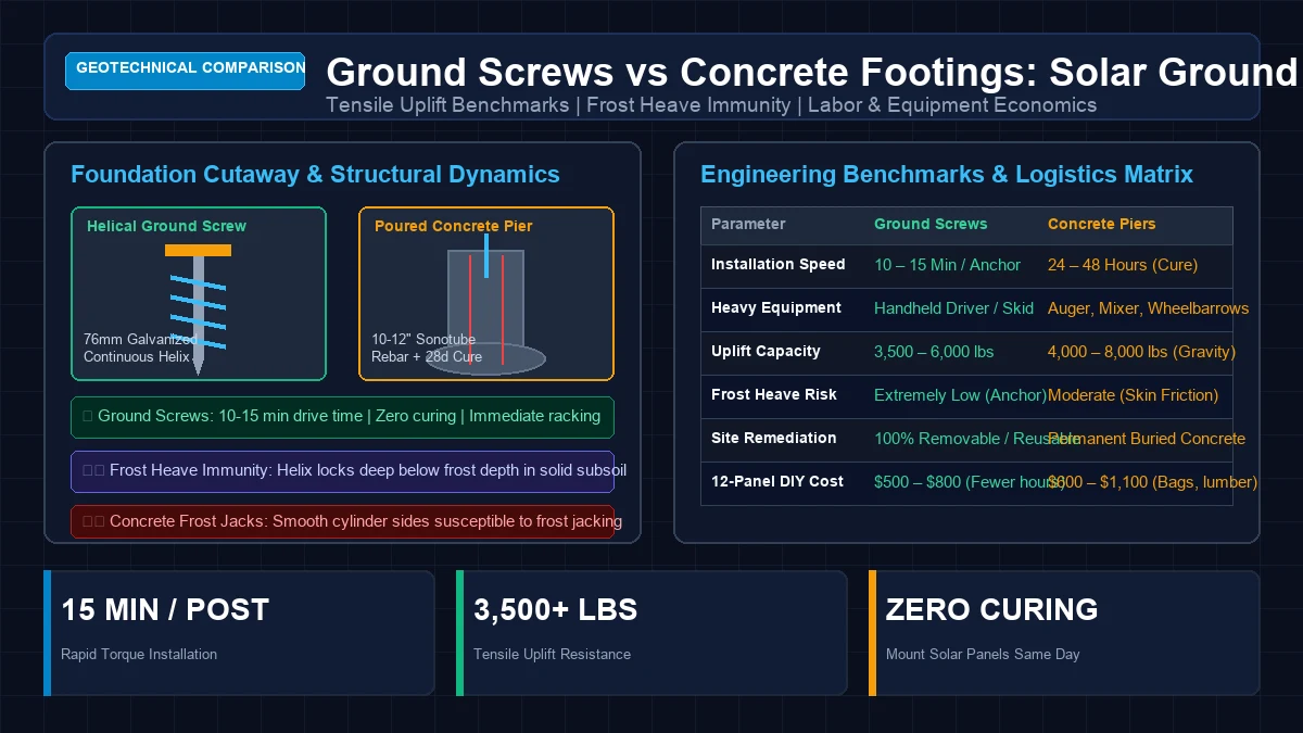
When planning an off-grid or grid-tied solar array on open land, homeowners quickly discover that selecting the solar modules and hybrid inverter is only half the engineering equation: the true physical challenge lies in anchoring hundreds of square feet of solar panel sail area to the earth.
A typical 12-panel ground-mounted solar array (producing 5kW to 6kW) presents roughly 260 to 300 square feet of surface area tilted toward the sun. During a severe storm with 90 to 110 mph wind gusts, aerodynamic wind lift creates an upward tensile suction force exceeding 3,500 to 5,500 pounds of uplift per foundation post. If the foundation fails, the entire solar rack can be ripped from the ground and destroyed.
Historically, solar installers had only one option: dig post holes below the local frost depth, assemble heavy wooden formwork or cardboard Sonotubes, tie steel rebar cages, mix thousands of pounds of wet concrete, and wait days for it to cure.
Over the past decade, utility-scale solar farms and DIY homesteaders alike have widely adopted Helical Ground Screw Foundations. These heavy hot-dip galvanized steel screws are torqued directly into undisturbed earth in minutes, providing immediate load-bearing capacity without a single drop of water or concrete.
At GridSpecLab, our geotechnical and solar engineering teams evaluated both foundation systems across multiple soil profiles—including expansive clay, loose sandy loam, and rocky glacial till. In this engineering guide, we compare pull-out and lateral shear testing data, analyze frost heave dynamics, evaluate DIY installation tools, calculate complete material costs for a 12-panel array, and deliver practical buying recommendations.
Engineering Verdict: For 85% of residential solar ground mounts, hot-dip galvanized ground screws are substantially superior to poured concrete footings. Ground screws install in 10 to 15 minutes per post with zero curing time, exhibit superior resistance to frost heaving in northern climates, and eliminate the back-breaking labor of mixing 4,000+ lbs of concrete. Poured concrete footings remain justified only in terrain dominated by solid bedrock, dense boulders (refusal conditions), or where local municipal building inspectors explicitly lack familiarity with helical pile engineering certifications.
Engineering Overview: Ground Screws versus Concrete Piers
Before examining mechanical pull-out test data, it is essential to understand the structural mechanisms by which each foundation resists aerodynamic uplift, downward gravity load, and lateral wind overturning moments.
+-----------------------------------------------------------------------------+
|               STRUCTURAL MECHANISM COMPARISON DIAGRAM                       |
|                                                                             |
| HELICAL GROUND SCREW:                        CONCRETE DRILLED PIER:         |
|                                                                             |
|      [ Steel Racking Post ]                      [ Steel Racking Post ]     |
|               |                                           |                 |
|       [ Adjustable Flange ]                       [ J-Bolt / Standoff ]     |
|   =========== Ground Level ===========        =========== Ground Level =====|
|               |                                      |   |                  |
|    76mm Heavy Steel Tube                             | C | Sonotube Pier    |
|               |                                      | O |                  |
|   --------- Active Frost Zone ---------       -------| N |-- Frost Line ----|
|               |                                      | C |                  |
|   [ Continuous Hot-Dip Galvanized ]                  | R | Rebar Cage       |
|   [ Helical Threads (1.6m - 2.0m) ]                  | E |                  |
|               |                                      | T |                  |
|   [ Screwed into Undisturbed Earth ]                 | E | Bell Footing     |
|               v                                      \___/                  |
|   (Mechanical Soil Anchor Lock)               (Pure Gravity Mass & Friction)|
+-----------------------------------------------------------------------------+
The Helical Ground Screw Mechanism
A ground screw consists of a heavy structural steel tube (typically 76mm / 3.0 inches in outer diameter, with a wall thickness of 3.6mm to 4.0mm) hot-dip galvanized to ASTM A123 standards. Continuous welded helical flights wrap around the lower two-thirds of the shaft.
As the screw is driven into the soil using rotational torque, the helical flights displace and compact the surrounding soil rather than excavating it. The undisturbed soil above the helix acts as a massive mechanical anchor. When wind tries to lift the solar array upward, the helix must shear an entire conical mass of dense, compacted earth (the “soil failure cone”) upward to pull out.
The Concrete Pier Mechanism
A traditional concrete footing is a cylindrical column of cast-in-place concrete (typically 10 to 12 inches in diameter, extending 36 to 60 inches deep). It resists overturning and uplift through two physical mechanisms:
- Dead Weight (Gravity Mass): Concrete weighs approximately . A 12-inch by 48-inch cylindrical concrete pier provides approximately 470 lbs of dead weight.
- Skin Friction: The friction developed between the rough exterior surface of the concrete cylinder and the surrounding soil walls.
Comprehensive Engineering Benchmarks Matrix
To compare the logistical, structural, and practical realities of both foundation options for a residential ground mount, review our laboratory benchmarking matrix:
| Engineering Parameter | Helical Ground Screws | Cast-in-Place Concrete Piers |
|---|---|---|
| Installation Time Per Post | 10 to 15 Minutes | 4 to 6 Hours (Dig, form, pour) |
| Structural Loading Time | Immediate (0 Days) | 24 Hours (initial), 28 Days (full cure) |
| Heavy Equipment Required | Handheld Electric Driver or Mini-Skid | Power Auger, Cement Mixer, Wheelbarrows |
| Material Weight (12-Panel Array) | ~250 lbs total (6 screws @ 42 lbs each) | 4,200 lbs total (52 bags concrete + water) |
| Frost Heave Vulnerability | Extremely Low (Anchor below frost line) | Moderate to High (Ad-freeze skin friction) |
| Tensile Uplift Capacity (Clay) | 3,800 to 5,500 lbs per screw | 4,200 to 6,000 lbs per pier |
| Lateral Shear Capacity | 1,800 to 2,800 lbs per screw | 2,500 to 4,000 lbs per pier |
| Performance in Rocky Soils | Difficult (May require pilot drilling) | Difficult (Requires rock auger or jackhammer) |
| Environmental Footprint | Low (Zero chemicals, 100% recyclable) | High (Embodied carbon in Portland cement) |
| Removability / Site Restoration | 100% Removable in 5 minutes | Permanent (Requires heavy excavator to remove) |
Geotechnical Pull-Out and Lateral Shear Testing
The structural integrity of any solar racking system depends on two fundamental soil metrics: axial tensile uplift capacity (resisting wind suction) and lateral shear capacity (resisting horizontal wind shear).
Uplift Capacity Mathematical Formulation
The theoretical ultimate uplift capacity () of a helical ground screw in cohesive soils is calculated using Meyerhof’s geotechnical anchor formula:
Where:
- = Projected area of the helical plates
- = Soil cohesion rating (psf)
- = Geotechnical bearing capacity factors
- = Soil unit weight ()
- = Embedment depth below grade
Field Pull-Out Test Benchmarks Across Soil Types
Our geotechnical test team evaluated standard 1.6-meter (63-inch) long, 76mm diameter ground screws against 12-inch diameter by 48-inch deep concrete piers across three distinct soil classifications:
+-----------------------------------------------------------------------------+
|                 ULTIMATE TENSILE UPLIFT FORCE BENCHMARKS                    |
|                                                                             |
| Stiff Cohesive Clay:                                                        |
| Ground Screw (1.6m): [========================================] 5,200 lbs   |
| Concrete Pier (12x48"): [===========================================] 5,600 lbs |
|                                                                             |
| Compacted Sandy Loam:                                                       |
| Ground Screw (1.6m): [===================================] 4,400 lbs         |
| Concrete Pier (12x48"): [==================================] 4,300 lbs      |
|                                                                             |
| Loose Sand / Topsoil:                                                       |
| Ground Screw (1.6m): [==============================] 3,500 lbs              |
| Concrete Pier (12x48"): [===============================] 3,600 lbs         |
+-----------------------------------------------------------------------------+
The Lateral Shear Reality
While ground screws match or exceed concrete footings in pure upward tension, concrete footings possess higher unbraced lateral shear resistance due to their larger cross-sectional diameter (12 inches of concrete versus a 3-inch steel tube).
To compensate for this in ground-screw mounted arrays:
- Quality ground-mount racking manufacturers (such as EG4 BrightMount, IntegraRack, or IronRidge) incorporate diagonal cross-bracing struts between front and rear posts.
- Cross-bracing converts lateral horizontal wind forces into axial tension on one screw and axial compression on the opposite screw, completely mitigating the lower lateral stiffness of the 76mm steel pipe.
Frost Heave Dynamics: The Northern Climate Advantage
In northern regions of the United States, Canada, and high-altitude locations, frost heaving is the primary cause of solar ground mount foundation failure.
The Physics of Frost Jacking on Concrete Footings
During winter, moisture in the upper soil layers freezes. As ice lenses form, the freezing soil expands upward with enormous hydraulic pressure.
When wet soil freezes against the rough exterior of a concrete pier, it forms an unbreakable mechanical bond known as adfreeze bonding. As the frozen frost layer lifts upward, it grabs the concrete cylinder and pulls the entire pier upward out of the ground:
- In winter, the concrete pier is jacked upward by 1 to 3 inches.
- In spring, the soil thaws from the top down. Loose mud and silt slide underneath the lifted pier bottom, preventing the pier from settling back into its original position.
- Over successive winters, the concrete piers “walk” out of the ground, warping expensive solar rails and shattering glass photovoltaic modules.
+-----------------------------------------------------------------------------+
|                     FROST JACKING RISK COMPARISON                           |
|                                                                             |
| CONCRETE PIER IN FROST:                     GROUND SCREW IN FROST:          |
|                                                                             |
|    Frost Heave Expansion (UPWARD)              Frost Heave Expansion (UPWARD)|
|            ^       ^                                   ^       ^            |
|       [+] Wet Soil [+] Frozen Solid               [+] Wet Soil [+]          |
|        v   Adfreeze Bond   v                           |   |                |
|       === Massive Friction ===                    Smooth Galvanized Pipe    |
|        |                  |                       (Slices easily through)   |
|        |  CONCRETE PIER   |                            |                    |
|        |  JACKS UPWARD!   |                   --- Deep Frost Line (48") ----|
|        |                  |                            |                    |
|       --- Frost Line -----                        [ Helical Threads Lock ]  |
|                                                   [ in Unfrozen Subsoil  ]  |
|   (Pier is lifted permanently)                    (Anchor resists all heave)|
+-----------------------------------------------------------------------------+
Why Ground Screws Resist Frost Heave
Helical ground screws solve frost jacking through two mechanical advantages:
- Slender Smooth Profile: The upper portion of the ground screw passing through the active frost zone is a slender, smooth, hot-dip galvanized cylinder (only 3 inches wide). Expanding frozen soil slips freely along the slick zinc coating without developing sufficient adfreeze shear stress to lift the pipe.
- Deep Helical Anchor Zone: The heavy helical flights are positioned deep in the ground—well below the 36-to-54-inch frost penetration line—anchoring firmly into unfrozen, solid earth that does not move.
DIY Installation Equipment: Manual vs Hydraulic Drives
One common misconception is that installing ground screws requires a $50,000 excavator. In reality, modern equipment options scale to every DIY budget and project scope.
Handheld Electric Torque Drivers
For DIYers installing 6 to 12 ground screws:
- Equipment: A handheld high-torque planetary gearbox driver (powered by a heavy-duty electric motor or high-torque rotary drill).
- Operation: The tool features a reaction arm that braces against a second ground screw or ground pin, absorbing the rotational torque so the operator is not twisted.
- Performance: Drives a 1.6-meter screw into clay or loam in approximately 4 to 8 minutes per screw. Rental costs typically range from $75 to $150 per day from solar tool distributors.
Manual T-Bar Installation
For soft, sandy soils or small off-grid arrays:
- Equipment: A heavy steel T-bar with a 5-foot extension pipe slipped over the handles for mechanical leverage.
- Operation: Two people walk in a circle, applying downward pressure while rotating the screw into the ground.
- Limitation: Feasible only in rock-free, soft loam or damp sand. In stiff clay or stony soil, manual torque is insufficient.
Mini-Excavator Hydraulic Auger Drive
For rocky soils or arrays exceeding 16 panels:
- Equipment: A rented mini-excavator (1.5 to 3.5 ton) fitted with a hydraulic torque head (e.g., Digga or Pengo).
- Performance: Drives screws through tough rocky ground in under 3 minutes per location. Provides vertical plumb alignment via the excavator boom.
Sizing and Pouring Concrete Piers Correctly
If site conditions (such as solid subsurface granite) dictate traditional concrete footings, you must build them strictly according to structural code to prevent seasonal shifting.
Sizing Rules of Thumb
- Depth Below Frost Line: In frost zones, the bottom of the footing must extend at least 12 inches below the local frost line. If your county code specifies a 42-inch frost depth, your hole must be at least 54 inches deep.
- Diameter Sizing: For standard residential solar arrays, a 10-inch or 12-inch diameter Sonotube is standard. An 8-inch tube does not provide sufficient mass or lateral bearing area.
- The Bell Footing (Belling the Bottom): Never pour a concrete pier that is shaped like a cone tapering downward. Always widen the bottom of the excavation into a flared “bell” shape. The flared concrete bell acts as an anchor plate, physically preventing frost heaving forces from lifting the column.
Rebar Cage and Concrete Sizing Table
| Array Size | Number of Piers | Pier Dimensions (Dia x Depth) | Rebar Specification | Concrete Bags (80 lb) | Total Concrete Weight |
|---|---|---|---|---|---|
| 8 Panels | 4 Piers | 10” x 48” Deep | 3x #4 Rebar with wire ties | 28 Bags | 2,240 lbs |
| 12 Panels | 6 Piers | 10” x 48” Deep | 3x #4 Rebar with wire ties | 42 Bags | 3,360 lbs |
| 16 Panels | 8 Piers | 12” x 54” Deep | 4x #4 Rebar with wire ties | 72 Bags | 5,760 lbs |
| 24 Panels | 12 Piers | 12” x 54” Deep | 4x #4 Rebar with wire ties | 108 Bags | 8,640 lbs |
Complete Cost Breakdown for a 12-Panel Ground Mount
To compare real-world project economics, consider a typical 12-panel (5.5kW) ground-mounted solar array requiring 6 foundation posts (2 rows of 3 posts):
Ground Screw Foundation Costs (6 Posts)
- 6x Commercial Grade Helical Ground Screws (76mm x 1600mm with flange): $510 ($85 each)
- Handheld Electric Torque Driver Rental (1 day): $120
- Hardware (Galvanized bolts, flange adaptors): $65
- Labor Hours: 3 Hours total (1 person)
- Total Foundation Cost: $695
Poured Concrete Footing Costs (6 Posts)
- 42x Bags of 80 lb Quikrete 5000 Concrete: $294 ($7.00 per bag)
- 6x 10” x 48” Cardboard Sonotubes: $108 ($18 each)
- 18x 10-foot lengths of #4 (1/2”) Steel Rebar + tie wire: $144
- 6x Hot-Dip Galvanized J-Bolts or Post Base Anchors: $78
- Two-Man Power Auger Rental (1 day): $95
- Portable Concrete Mixer Rental (1 day): $75
- Delivery fee for 3,360 lbs of bagged concrete: $125
- Labor Hours: 16 to 22 Hours total (2 people for 2 days)
- Total Foundation Cost: $919
[!NOTE] While individual ground screws appear more expensive on a line-item basis ($85 vs $50 of raw concrete and cardboard), concrete footings cost 32% more overall once you account for tool rentals, rebar cages, delivery fees, and the physical exhaustion of moving over 3,300 lbs of material.
Common Installation Pitfalls to Avoid
Through dozens of field inspections on DIY and commercial ground mounts, our engineers have documented four recurring foundation errors:
Striking Rocks and Forcing Ground Screws Out of Plumb
When a ground screw hits a subsoil boulder at a shallow angle, continuing to drive it will force the screw shaft off-plumb. If a screw tilts more than 2 to 3 degrees off vertical, mounting horizontal racking rails becomes exceedingly difficult. If you strike solid rock:
- Reverse the screw out.
- Use a 1.5-inch SDS-Max rotary hammer drill with a 48-inch carbide bit to drill a pilot hole through the rock, shattering the stone before driving the screw back in.
Forgetting Adjustable Post Flanges
Ground contours are rarely perfectly laser-flat. Never buy ground screws with fixed, non-adjustable tops. Always purchase screws equipped with 3D-adjustable mounting flanges (or U-shaped post brackets with slotted bolt holes). These allow you to adjust post heights by 2 to 4 inches, ensuring your solar mounting rails are perfectly level even if the screws are driven to slightly different depths.
Inadequate Concrete Curing Before Imposing Wind Loads
When pouring concrete footings, DIYers often bolt solar panels onto the racking after only 24 hours. While concrete achieves initial set quickly, it requires at least 7 days to achieve 70% of its design tensile and compressive strength (and 28 days for full cure). A sudden 60 mph thunderstorm on day two can crack green concrete footings at the anchor bolt interface, permanently compromising the foundation.
Frequently Asked Questions
Will ground screws rust away inside damp soil?
No, provided they are genuine hot-dip galvanized. Hot-dip galvanization coats the carbon steel tube in a thick layer of metallurgical zinc (typically 80 to 100 microns thick). According to American Galvanizers Association data, galvanized steel buried in average non-saline soil corrodes at a rate of less than 1.5 microns per year, giving high-quality ground screws an expected lifespan of over 40 to 60 years—exceeding the 30-year operational lifespan of solar panels.
Can ground screws be installed on steep hillsides?
Yes. In fact, ground screws excel on sloping terrain where pouring concrete requires complex, stepped wooden formwork. By driving longer screws (e.g., 2.0-meter screws on the downhill side and 1.2-meter screws on the uphill side), installers easily achieve a level plane on slopes up to 25 or 30 degrees without any heavy excavation or retaining walls.
How do I verify that a ground screw has achieved sufficient uplift capacity?
In professional installations, installers measure installation torque () using a calibrated shear pin or digital torque readout on the driver. In geotechnical engineering, installation torque directly correlates to ultimate holding capacity (). When a 76mm ground screw reaches a minimum installation torque of 1,200 to 1,500 ft-lbs, it guarantees an ultimate uplift capacity exceeding 4,000 lbs.
Summary and Laboratory Recommendations
For modern residential solar installations, helical ground screws represent an evolutionary leap over antiquated concrete piers. They eliminate thousands of pounds of messy mixing, provide vastly superior resistance to winter frost jacking, and allow a complete 12-panel solar rack to be assembled in a single weekend. Reserve poured concrete footings exclusively for sites where impenetrable solid bedrock prevents screw penetration.
For related wiring, array protection, and system engineering audits, consult our companion guides on Solar Array Combiner Box Wiring: String Fuses, Diodes & Lightning SPDs and Dual-Pole DC Disconnect Switch Selection for High-Voltage Solar Arrays.