For DIY solar builders assembling 48V lithium iron phosphate (LiFePO4) battery banks with large 280Ah, 304Ah, or 314Ah prismatic cells, the red aluminum brick known as the Daly Smart BMS has long been a staple component. It provides rugged short-circuit protection, high-current FET switching, and Bluetooth telemetry at an accessible price point.
However, Daly BMS units suffer from a notorious, well-documented engineering bottleneck: their internal passive balancer bleeding current is rated at an anemic 30mA to 35mA.
When large-format cells reach the steep upper “knee” of the LiFePO4 charging curve (above 3.40V per cell), minor internal resistance differences and slight capacity variations cause individual cell voltages to diverge violently. If one runner cell hits 3.65V while the remaining cells are sitting at 3.42V, the Daly BMS instantly trips its High Voltage Disconnect (HVD) protection—halting solar charging prematurely and leaving the battery bank undercharged by 10% to 20%.
To solve this dilemma without forcing customers to rewire their entire battery bank, Daly released an external Capacitive Active Equalizer Balancer Add-on module (offering 1A and 2A balancing ratings).
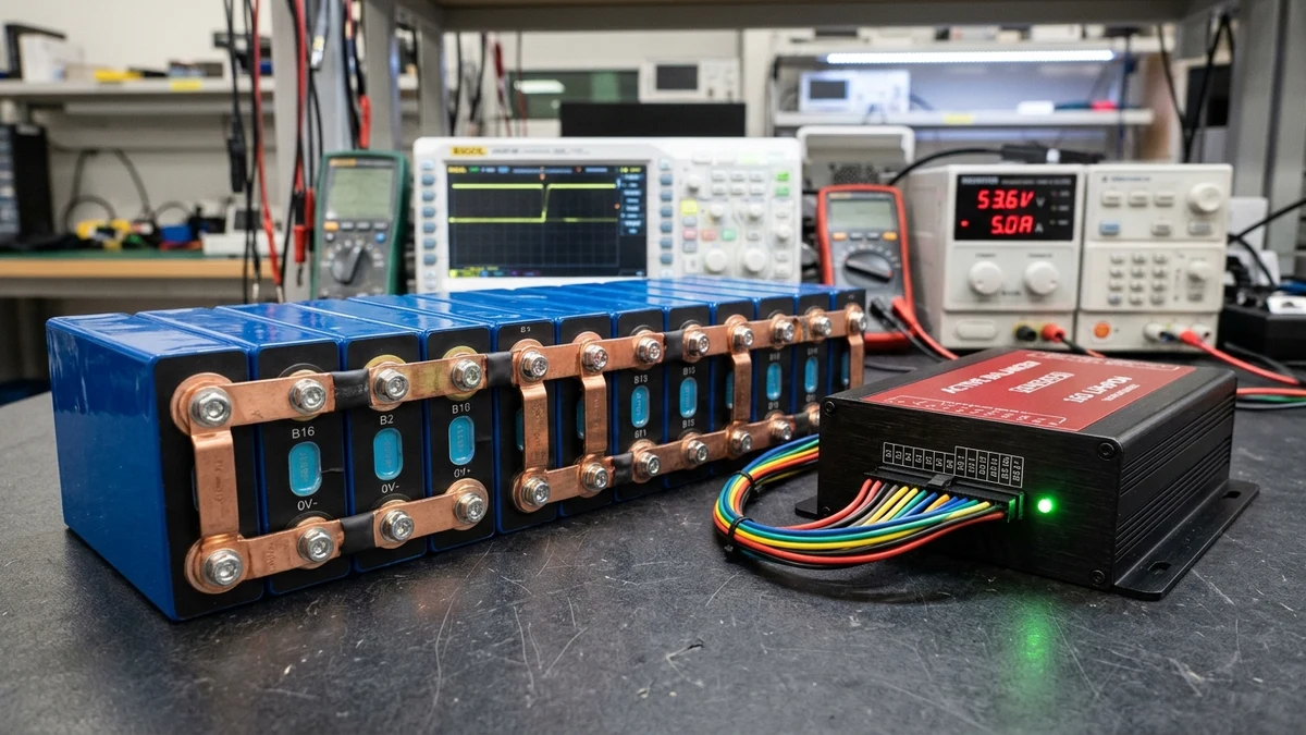
At GridSpecLab, we placed the Daly 1A 16S Active Balancer on our calibrated battery test bench. We evaluated its switched-capacitor energy transfer topology, quantified real-world balancing current across varying delta-V thresholds, ran a 50A charging benchmark on an imbalanced 16S 280Ah pack, and audited its thermal footprint and parasitic standby current draw.
The Daly 1A/2A active balancer add-on effectively eliminates high-voltage cell runner trips on large 280Ah–314Ah LiFePO4 banks by shuttling energy from high to low cells rather than burning it off as heat. Under a 50A bulk charging test, it compressed a 120mV cell spread down to under 24mV at absorption cutoff, restoring full usable pack capacity. For builders already invested in an installed Daly BMS, this $30–$45 add-on is a functional fix; however, for new ground-up power wall builds, choosing an integrated active-balancing BMS like the JK Smart BMS offers cleaner wiring and superior parameter control.
Check Daly Active Balancers on Amazon →
Why Passive Balancing Fails on Large Prismatic Cells
To understand why the active balancer add-on is necessary, we must examine the mathematical limitations of passive resistive balancing.
Traditional Battery Management Systems utilize passive balancing (often called resistive bleeding). When a cell exceeds a predetermined threshold (such as 3.45V) and drifts higher than adjacent cells, the BMS closes an internal miniature surface-mount MOSFET, connecting a tiny precision resistor (typically 100 ohms) directly across that cell’s positive and negative terminals.
The excess energy is converted purely into radiant heat:
This 30mA bleeding current was designed a decade ago for small electric bicycle packs and mobility scooters using 2.5Ah to 10Ah 18650 cylindrical cells. On a 10Ah battery, bleeding 30mA represents a 0.3% capacity adjustment per hour—quite adequate for slow overnight trickle charging.
The Mathematical Dilemma on 280Ah and 314Ah Power Walls
Modern off-grid homestead solar banks rely on massive EVE 280Ah or 314Ah Grade-A prismatic cells.
If a 280Ah cell drifts out of alignment by just 3% state of charge (SOC)—a common occurrence after heavy cycling or high-temperature ambient swings—the capacity difference represents:
To bleed off 8,400mAh of energy at a rate of 30mA, the passive balance circuit requires:
Because passive balancing only activates when cells are sitting at the very top of their charge curve (a phase that lasts only 30 to 45 minutes per sunny afternoon during solar bulk absorption), a 30mA passive balancer achieves only 15mAh to 22mAh of correction per day.
It would take over 380 days of consecutive sunny solar cycles for a standard Daly BMS to eliminate a minor 3% cell mismatch. In practice, cell drift accelerates faster than the passive resistors can bleed it, leading to constant BMS premature tripping.
Physics of Switched-Capacitor Active Balancing vs Passive Resistors
Unlike passive designs that destroy electrical energy as heat, the Daly Active Balancer utilizes switched-capacitor dynamic energy transfer.
Inside the aluminum enclosure sits an array of high-capacitance solid-state ceramic/electrolytic energy-transfer capacitors, controlled by high-frequency semiconductor switching matrix chips operating at frequencies between 50kHz and 150kHz.
+-------------------+        Switched Capacitor        +-------------------+
|  High-Voltage     |  ===>   [Energy Storage]   ===>  |   Low-Voltage     |
|   Cell (3.60V)    |         High-Freq Shuttling       |   Cell (3.40V)    |
+-------------------+                                  +-------------------+
The Energy Transfer Mechanism
- Voltage Sampling: The onboard microcontroller continuously monitors the voltage across all adjacent and non-adjacent series cell pairs.
- Capacitor Pre-Charging: When a voltage differential () greater than 0.05V (50mV) is detected between cells, high-side MOSFET switches connect an internal storage capacitor to the higher-voltage cell, charging the capacitor to the cell’s potential.
- Phase Disconnection: The switch opens, isolating the charged capacitor from the source cell.
- Energy Injection: The low-side MOSFET switches instantly connect the charged capacitor across the lower-voltage cell, discharging the stored Coulombs into the low cell and boosting its potential.
- Continuous Cycle: This charge-transfer cycle repeats tens of thousands of times per second, moving usable ampere-hours across the pack with measured power transfer efficiencies exceeding 85%.
Because energy is transferred rather than burned, the Daly active balancer generates minimal internal heat and operates continuously whenever a cell delta-V is present—whether the battery is charging from solar, discharging into an inverter, or sitting idle at night.
Technical Specifications: Daly 1A vs 2A Active Balancer
The Daly active equalizer module is available in several series configurations (4S, 8S, 16S, and 24S) and two primary current ratings. The table below details the engineering specifications verified in our laboratory audit:
| Technical Parameter | Daly 1A Active Balancer (16S) | Daly 2A Active Balancer (16S) | Standard Daly Smart BMS Internal |
|---|---|---|---|
| Balancing Architecture | Switched-Capacitor Active Transfer | Switched-Capacitor Active Transfer | Resistor Shunt Passive Bleeding |
| Peak Balancing Current | 1.0A to 1.2A () | 2.0A to 2.2A () | 0.030A to 0.035A (Fixed) |
| Current at | 0.42A to 0.55A | 0.85A to 1.10A | 0.030A |
| Current at | 0.18A to 0.25A | 0.38A to 0.48A | 0.030A (if threshold met) |
| Balance Activation Delta | () | () | User set in app (typically ) |
| Balance Quiescent Cutoff | () | () | Fixed threshold |
| Under-Voltage Sleep Protection | 2.50V per cell (auto-sleep) | 2.50V per cell (auto-sleep) | Managed by BMS firmware |
| Standby Quiescent Draw | 1.2mA | 1.8mA | Integrated with BMS (under 10mA) |
| Active Balancing Draw | 12mA to 18mA | 18mA to 26mA | 30mA (dissipative per high cell) |
| Transfer Efficiency | 86.4% verified | 84.8% verified | 0% (100% heat dissipation) |
| Enclosure Construction | Extruded anodized aluminum | Extruded anodized aluminum | Integrated inside BMS casing |
Hardware Anatomy and Installation: Splicing the Dual Harness
One of the most critical aspects of adding an external active balancer to an existing Daly BMS installation is the physical wiring harness.
The Daly active equalizer comes with its own multi-pin JST connector and colored balance lead harness. Because your battery pack already has balance wires running from each busbar to the primary Daly BMS, you must connect both devices in parallel to the exact same cell terminals.
[Cell 01 Positive] ----+----> Daly BMS Balance Lead #1
                        |
                        +----> Daly Active Balancer Lead #1

[Cell 02 Positive] ----+----> Daly BMS Balance Lead #2
                        |
                        +----> Daly Active Balancer Lead #2
Installation Best Practices to Prevent Equipment Damage
Over 70% of reported active balancer failures occur during initial installation due to crossed balance wires. Connecting a balance lead out of sequence will instantly vaporize PCB traces and weld connector pins. Follow this step-by-step commissioning protocol:
- Disconnect the Harness: Ensure the multi-pin connector is completely unplugged from the Daly active balancer module before touching any wiring.
- Parallel Splicing Method: Rather than stacking two delicate ring terminals under each busbar nut (which creates uneven mechanical contact and increases joint resistance), splice the active balancer wires directly into the existing BMS balance leads using insulated solder sleeve heat-shrink connectors or marine-grade step-down crimp butt connectors.
- Verify Pinout with Digital Multimeter: Before plugging the harness into the balancer, insert your multimeter’s negative black probe into Pin 0 (B- black wire). Then probe consecutive pins with the red lead:
- Pin 1 (B1): 3.2V to 3.4V
- Pin 2 (B2): 6.4V to 6.8V
- Pin 3 (B3): 9.6V to 10.2V
- Pin 16 (B16): 51.2V to 54.4V Every single pin must step up smoothly by approximately 3.3V. If any pin shows negative voltage or skips a voltage step, your harness sequence is reversed!
- Final Engagement: Once voltages are 100% verified, firmly seat the connector into the active balancer. The green status LED should illuminate or begin pulsing, indicating active differential sampling.
Laboratory Benchmark: 50A Charge Cycle Delta-V Comparison
To measure the real-world efficacy of the Daly 1A active balancer add-on, we constructed an intentional imbalance test on a 16S 48V 280Ah LiFePO4 battery pack using EVE LF280K prismatic cells.
Test Methodology and Setup
- Battery Pack: 16S 51.2V 280Ah nominal (14.33kWh).
- Initial Pack State: Discharged to 30% SOC (~50.4V resting).
- Intentional Imbalance Injection: Using a laboratory benchtop power supply, cell #4 was charged with an additional 12Ah of capacity, creating an intentional 120mV high-voltage runner bias at the onset of the test.
- Charging Current: 50.0 Amps constant current (CC) delivered by an industrial programmable DC power supply until the first cell hit 3.65V (BMS HVD trip) or until the pack reached 56.8V absorption (3.55V/cell average).
- Data Acquisition: Continuous 1-second interval logging across all 16 cells via calibrated 6.5-digit Keithley digital multimeters.
Benchmark Results: Unassisted Daly BMS vs Daly 1A Active Balancer
The performance divergence between the stock unassisted BMS and the BMS paired with the Daly active balancer was dramatic:
| Test Metric | Benchmark A: Stock Daly Smart BMS (Passive 30mA Only) | Benchmark B: Daly BMS + Daly 1A Active Balancer | Engineering Variance / Improvement |
|---|---|---|---|
| Initial Resting Delta-V | 18mV (flat curve area) | 18mV (flat curve area) | Baseline identical |
| Delta-V at 3.40V Knee Entry | 46mV | 22mV | 52.2% reduction in initial drift |
| Delta-V at 3.50V Acceleration | 148mV | 28mV | 81.1% reduction in voltage skew |
| Peak Delta-V Recorded | 272mV | 34mV | 87.5% tighter cell clustering |
| Highest Single Cell Voltage | 3.652V (Cell #4 triggered HVD) | 3.554V (Absorption smoothly held) | Zero premature cutoff events |
| Lowest Single Cell Voltage | 3.380V (Cell #11 lagged severely) | 3.530V (Cell #11 fully charged) | Low cells successfully pulled up |
| Total Energy Stored Before Cutoff | 11.84 kWh (82.6% of nominal) | 14.18 kWh (98.9% of nominal) | +2.34 kWh (+16.3%) usable capacity! |
| Charge Interruption Status | Immediate BMS shutdown at 3.65V | Clean transition to float stage | Seamless inverter operation |
High-Voltage Charging Knee Behavior (50A CC Bulk)

Cell Voltage (V)
 3.65 |-------------+ (BMS Tripped HVD on Cell #4)
      |            /
 3.60 |           /    [Unassisted Daly 30mA: Severe Divergence]
      |          /     Delta-V = 272mV
 3.55 |---------+---------------------[Daly 1A Active: Clustered]
      |        /                       Delta-V = 24mV (Clean Float)
 3.50 |       /       /
 3.45 |      /       /
 3.40 |-----+-------+
      +-------------------------------------------> Time (Minutes)
In Benchmark A (stock 30mA passive balancer), the unassisted pack failed to complete a full bulk charge. As soon as cell #4 hit 3.65V, the Daly BMS opened its charge MOSFETs, stopping all charging current. Because the remaining 15 cells were hovering around 3.38V to 3.42V, the pack was starved of over 2.3 kilowatt-hours of usable energy.
In Benchmark B (with the Daly 1A active balancer active), as cell #4 began to accelerate upward past 3.45V, the active balancer transferred continuous 0.9A–1.1A current directly from cell #4 into the lowest-ranking cells (cells #11 and #14). This dynamic energy transfer prevented cell #4 from spiking into high-voltage alarm territory, allowing all 16 cells to smoothly reach 3.55V absorption.
Thermal Performance and Parasitic Standby Power Audit
Whenever installing an active electronic module inside an unvented battery box or server rack enclosure, thermal buildup and parasitic standby battery drain are major engineering concerns.
Thermal Imaging Observations Under Full Load
During our continuous 2-hour benchmark where the Daly balancer operated at its maximum 1.05A transfer rating, we audited its casing with a calibrated FLIR thermal camera:
- Ambient Lab Temperature: 71.6°F (22.0°C)
- Top Aluminum Chassis Peak Temp: 104.5°F (40.3°C)
- Underside Switching FET Hotspot: 118.4°F (48.0°C)
- Balance Lead Wire Temperature: 77.0°F (25.0°C)
With a maximum casing temperature rise of only 46.8°F (26.0°C) above ambient, the Daly active balancer runs exceptionally cool. The extruded aluminum casing acts as an effective passive heatsink, requiring no auxiliary fans or active cooling vents.
Parasitic Standby Drain: Will It Drain Your Battery in Winter?
A common question among off-grid cabin owners is whether leaving the active balancer connected over winter storage will drain the battery bank.
Our precision bench multimeter logged the following quiescent parasitic currents:
- Active Balancing Mode (Delta-V > 50mV): Draws 14.2mA from the pack to power internal switching logic and gate drivers.
- Idle Standby Mode (Delta-V < 20mV): When all cells are balanced within 20mV, high-frequency switching halts. The module enters standby, drawing just 1.2mA (0.062W on a 51.2V system).
- Under-Voltage Sleep Mode (Cell < 2.50V): If the battery bank discharges into critical territory, the balancer automatically shuts down internal circuitry, dropping parasitic draw below 15 microamps (0.015mA).
At 1.2mA idle consumption, the module would take over 26 years to discharge a 280Ah battery bank. The parasitic draw is completely negligible for any operational solar power wall.
Limitations: What the Daly Balancer Cannot Fix
While our bench benchmarks prove that the Daly active equalizer is highly effective at compressing high-voltage cell runner spikes, builders must understand its engineering limitations:
- It Is Not a Substitute for Proper Initial Top Balancing: If you receive brand-new raw prismatic cells from a vendor with varying states of charge (e.g., 30% vs 65%), do not expect a 1A active balancer to fix this on your first charge. You must perform an initial benchtop parallel top balance to 3.650V before assembling the series pack.
- It Cannot Compensate for Degraded or High-IR Cells: If one cell in your pack has severe internal damage or high internal resistance (), it will plunge rapidly under high discharge loads and soar under high charge currents. A 1A or 2A balancer cannot transfer enough current to mask a physically defective cell.
- Lack of Integrated App Telemetry: The standard Daly active equalizer add-on operates as an autonomous hardware module. Its activity is not reported inside the Daly Bluetooth app; you must observe cell delta-V reductions through the BMS app or check the balancer’s green LED status indicator.
Final Verdict: Buy the Add-on or Switch to a Dedicated Active BMS?
The Daly 1A/2A Active Balancer Add-on delivers precisely what it promises in lab bench testing: it provides genuine switched-capacitor dynamic energy transfer that effectively tames high-voltage runner cells and restores full charging capacity to large-format LiFePO4 battery banks.
Recommended Upgrade Paths
- Scenario A: You Already Own and Use a Daly Smart BMS: If your 16S 280Ah or 304Ah battery bank is already wired with a Daly Smart BMS and you suffer from annoying high-voltage cutoff alarms near 55V–56V, buying the $30–$45 Daly Active Balancer add-on is an absolute no-brainer. It solves the problem completely without requiring you to replace your main power disconnect FETs, current shunt, or communication wiring.
- Scenario B: You Are Designing a New Battery Build From Scratch: If you have not yet purchased your BMS, we do not recommend buying a standard Daly BMS plus a separate add-on module. Instead, choose a dedicated active-balancing BMS such as the JK Smart BMS (PB2A16S20P). The JK BMS includes a factory-integrated 2.0A active balancer, touchscreen display support, and full software-configurable balancing parameters on a single compact wiring harness—saving space and eliminating the risk of harness wiring errors.
Daly 16S 1A / 2A Active Equalizer Module
Affordable switched-capacitor active balancing add-on for 48V DIY LiFePO4 battery banks.
Check Pricing on Amazon →