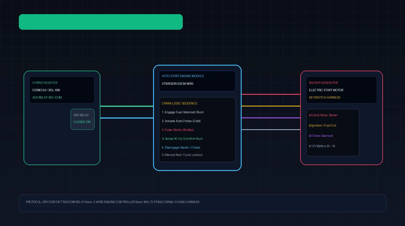
One of the greatest milestones in building an autonomous off-grid power system is achieving seamless generator auto-start. When several consecutive days of heavy cloud cover or dense winter snow deplete your battery bank below a critical threshold, a properly automated system commands your standby generator to start, run through warm-up, replenish the battery bank at high efficiency, and shut down cleanly—all without human intervention.
However, bridging the brain of an advanced solar inverter to an internal combustion engine is where many DIYers run into confusion. Most hybrid inverters feature a simple pair of screw terminals labeled “Generator Auto-Start” or “Aux Relay”. Novice builders often assume these terminals supply 12V or 120V to crank the generator. In reality, they are strictly voltage-free dry contacts.
Connecting dry contacts directly to a standard key-switch portable generator will either short out control electronics or do nothing at all. In this technical engineering guide, we dissect the mechanics of inverter dry contacts, detail the interface circuitry needed to manage starter and choke solenoids, provide complete wiring schematics, and walk through programming parameters for Victron, Sol-Ark, and EG4 systems.
An inverter’s generator auto-start port is a simple switch (NO/COM), not a power source. When battery SoC drops below your setpoint, the internal relay closes. To turn this steady closed circuit into an engine-starting sequence (ignition ON → choke pull → starter crank → AC voltage sensing → warm-up), you must install a 2-Wire to Multi-Wire Auto-Start Controller (such as the Atkinson GSCM-mini) between the inverter and any standard key-start generator.
Explore Tested Solar Generators →
Principles of Inverter Dry-Contact Relays
To design a reliable auto-start system, you must first understand the fundamental electrical behavior of the inverter’s auxiliary output.
A dry contact (or voltage-free contact) is a relay contact where no internal voltage is present on either terminal. The inverter acts merely as a switch in an external circuit. Inside the inverter chassis, a micro-relay connects two pins:
- COM (Common): The incoming control wire.
- NO (Normally Open): The outgoing control wire that connects to COM when the relay energizes.
- NC (Normally Closed): An optional third contact present on select inverters (e.g., Victron Cerbo GX Relay 1) that is connected to COM at rest and disconnects when energized.
When the inverter determines the battery requires auxiliary charging, its internal microcontroller energizes the relay coil. The contact closes, creating a continuous low-resistance electrical bridge between COM and NO.
       INVERTER INTERNAL                   EXTERNAL AUTO-START CIRCUIT
   [ Microcontroller ]
            |
      (Relay Coil)
            |
         [ COM ] ------------------------> [ Control Signal Wire A ]
            o                                         |
             \  (Contact Closes on Trigger)           v
            o                                [ 2-Wire Engine Controller ]
         [ NO  ] ------------------------> [ Control Signal Wire B ]
Dry Contact Electrical Limitations
While dry contacts can switch control voltages safely, they have strict physical ratings:
- Voltage Limit: Typically rated for up to 30V DC / 250V AC.
- Current Limit: Usually capped at 3A to 5A continuous resistive load.
- Inductive Inrush Hazard: Connecting an inverter relay directly to a heavy engine starter solenoid (which draws 15A to 30A inrush) will instantly weld the microscopic silver contacts together, causing the starter motor to crank continuously until the generator starter burns out or the battery explodes.
Two-Wire Commercial vs Three-Wire Key-Start Generators
The exact interface wiring required depends on the factory configuration of your generator. Generators broadly fall into two engineering categories:
Native Two-Wire Auto-Start Generators
Premium standby generators—such as Generac Guardian, Kohler RESV, Cummins Onan, and industrial diesel units—come from the factory with built-in engine control modules (ECMs).
These generators already feature dedicated two-wire start terminals. When an external contact bridges their two start terminals, the internal ECM automatically manages fuel priming, glow plugs, starter cranking, oil pressure monitoring, and fault lockouts.
If you own a native two-wire generator:
- Run a 2-conductor 14 AWG or 16 AWG cable directly from the inverter’s
COMandNOterminals to the generator’s two remote start pins. - No external controllers or intermediate relays are needed.
Standard Electric Key-Start Portable Generators
The vast majority of off-grid solar builders utilize portable inverter generators or dual-fuel models (e.g., Champion 100111, Predator 9500, or Westinghouse WGen12000DF).
These units feature an ignition key or push-button that requires a multi-step sequence:
- Turn Ignition and Fuel Solenoid ON (steady 12V).
- Engage Choke Solenoid if ambient temperature is cold (momentary 12V).
- Engage Starter Solenoid (momentary 12V for 3 to 8 seconds until combustion occurs).
- Disengage Starter Solenoid immediately when the engine catches to prevent flywheel damage.
- Release Choke as engine reaches operating temperature.
- Open Ignition Circuit to ground out the magneto or shut off the fuel solenoid to stop the engine.
An inverter dry contact cannot perform this dynamic sequence by itself. It maintains a single continuous closed circuit. To translate that static closure into an autonomous starting sequence, you must install an Engine Control Module.
Interfacing with an Engine Control Module: Atkinson GSCM-mini
The industry gold standard for converting a 2-wire inverter signal into a multi-wire engine control sequence is the Atkinson Electronics GSCM-mini (Generator Start Control Module).
+-------------------------------------------------------------------------------+
|                       ATKINSON GSCM-mini WIRING TOPOLOGY                      |
+-------------------------------------------------------------------------------+

       [ HYBRID INVERTER ]
      +-------------------+
      |  [COM]     [NO]   |
      +----+---------+----+
           |         |   (Shielded 14 AWG 2-Wire Run)
           v         v
      +----+---------+----+
      |  [IN1]     [IN2]  |  <-- 2-Wire Dry Contact Input Loop
      |                   |
      |   ATKINSON GSCM   |
      |    MICRO-LOGIC    |
      |                   |
      | [B+]  [B-]  [IGN] |  <-- 12V Battery Power & Run Command
      | [CRK] [CHK] [SEN] |  <-- Crank, Choke, and AC Frequency Sense
      +--+-----+--+----+--+
         |     |  |    |
         |     |  |    +-----> AC 120V Hot (Senses Engine Running)
         |     |  +----------> Choke Solenoid (12V Pulse)
         |     +-------------> Starter Solenoid Relay (Crank 12V Pulse)
         +-------------------> Ignition / Fuel Solenoid (Continuous 12V)
The Autonomous Cranking State Machine
When the inverter closes the 2-wire contact across IN1 and IN2, the GSCM-mini executes a failsafe hardware algorithm:
- Pre-Ignition Warmup: Powers the generator’s 12V ignition module and fuel cut-off solenoid.
- Choke Actuation: If cold-start mode is configured, it fires a 12V pulse to pull the carburetor choke arm closed.
- Crank Attempt: Sends a high-current trigger to the starter relay for 5 to 8 seconds.
- AC Run Detection: The module monitors an AC sensing wire connected to the generator’s 120V output receptacle. The moment it detects 60Hz AC voltage above 80V, it instantly drops the starter motor relay.
- Rest and Retry: If the engine fails to start on the first attempt, the module pauses for 10 seconds to allow the starter motor to cool, then re-attempts up to three cranking cycles.
- Fault Lockout: If three crank cycles fail, the module enters a safety lockout mode, cutting the ignition to prevent battery drain or carburetor flooding, and lights an amber fault LED.
- Shutdown Sequence: When the inverter opens the 2-wire contact, the module de-energizes the fuel/ignition relay, allowing the engine to spin down to a complete halt.
Complete Wiring Schematic and Terminal Pinouts
Below is the standard wiring schedule for connecting a hybrid inverter, an Atkinson GSCM-mini controller, and an electric-start portable generator.
| GSCM Terminal | Wire Color Standard | Destination Hardware | Functional Description |
|---|---|---|---|
| Input 1 (IN1) | Blue | Inverter Relay COM | Dry-contact input signal loop wire A |
| Input 2 (IN2) | Blue / White | Inverter Relay NO | Dry-contact input signal loop wire B |
| Battery (+) B+ | Red (14 AWG) | Generator Starter Lug / Battery (+) | Fused 12V DC power supply to module (Use 5A Fuse) |
| Battery (-) B- | Black (14 AWG) | Generator Frame / Battery (-) | Common DC ground return |
| Ignition (IGN) | Yellow (14 AWG) | Generator Key Switch Run Terminal | Sustained 12V output to fuel solenoid and ignition coil |
| Starter (CRK) | Orange (14 AWG) | Starter Solenoid Trigger Pin | Momentary 12V crank pulse during starting cycle |
| Choke (CHK) | Violet (14 AWG) | 12V Choke Solenoid | 2-to-5 second pulse to close carburetor choke flap |
| AC Sense (SEN) | White (16 AWG) | Generator 120V AC Hot (L1) | AC frequency sensor confirms engine is running |
Tapping the Generator Key Switch Harness
To connect the module’s outputs to a portable generator without cutting the factory wiring harness:
- Locate the rear of the key switch or push-button ignition module.
- Use a digital multimeter set to DC volts to probe the terminals:
- Constant 12V: Measures 12.6V DC at all times directly from the starter battery.
- Ignition / Run: Measures 0V when the key is OFF, and 12V when the key is turned to ON. Connect GSCM
IGNwire here. - Start / Crank: Measures 12V only while holding the key in the momentary START position. Connect GSCM
CRKwire here.
- Install weatherproof spade taps or soldered inline tap splices wrapped in dual-wall adhesive heat shrink tubing.
Inverter Programming: Victron, Sol-Ark, and EG4 Configurations
Wiring the hardware correctly is only half the battle. You must program the inverter’s energy management software to govern when the generator should engage and disengage.
State of Charge (SoC%) vs Pack Voltage Triggers
Always trigger generator auto-start using Battery SoC% via closed-loop BMS communications whenever possible.
Triggering solely on battery pack voltage introduces severe flaws:
- Voltage Sag Distortion: When heavy household loads start (e.g., a 4,500W well pump or 3,000W clothes dryer), battery terminal voltage temporarily sags by 1.5V to 2.5V, even if the battery has 70% capacity remaining. A voltage-based trigger will falsely crank the generator unnecessarily.
- LiFePO4 Discharge Curve Flatness: Between 80% and 20% SoC, a 48V LiFePO4 battery’s resting voltage drops only from 53.0V to 52.4V (a difference of just 0.6V across 60% of capacity). Measuring SoC% eliminates voltage curve ambiguity.
+--------------------------------------------------------------------------------+
|                   RECOMMENDED INVERTER AUTO-START THRESHOLDS                   |
+--------------------------------------------------------------------------------+

   100% SoC +------------------------------------------+
            | Normal Daily Operation (Solar Dominant)   |
    80% SoC +------------------------------------------+ <-- Generator Stop Point
            |                                          |     (Leaves headroom for
            | Reserve Battery Operating Band           |      solar charging)
            |                                          |
    25% SoC +------------------------------------------+ <-- Generator Start Point
            | Emergency Battery Buffer (15-20%)        |     (Prevents BMS Cutoff)
     0% SoC +------------------------------------------+
Victron Energy (Cerbo GX / Color Control GX) Configuration
In Victron’s Venus OS:
- Navigate to Settings → Generator start/stop → Settings.
- Set Measurement to
Battery SoC. - Set Start value to
25%(or30%in winter climates). - Set Stop value to
80%. Do not charge to 100% via generator; leave the final 20% absorption phase for solar generation to avoid running an engine under light load. - Enable Quiet Hours: Set quiet hours from 22:00 (10:00 PM) to 07:00 (7:00 AM). During quiet hours, set the emergency start threshold to
15%SoC to ensure sleep is not interrupted unless the battery faces critical shutdown.
Sol-Ark 15K-2P Configuration
On the Sol-Ark touchscreen:
- Tap the gear icon → Aux Load / Gen Setup → Select Generator Input.
- Select Auto Start By Battery %.
- Set Start Battery % to
25%and Start Battery V to48.0Vas a failsafe backup. - Set Stop Battery % to
85%. - Enter Generator Max Run Time: Set to
360 minutes(6 hours) to prevent the generator from running through a full tank of fuel if the battery BMS disconnects. - Enter Min Run Time: Set to
30 minutesto ensure the generator reaches full engine operating temperature, burning off moisture in the crankcase oil.
EG4 18kPV Configuration
In the EG4 monitoring app or on-screen interface:
- Navigate to Maintenance → Auxiliary Relay Setup.
- Choose Generator Control Function.
- Set Start SoC to
20%and Stop SoC to80%. - Configure Warm-up Time: Set to
120 seconds. This forces the inverter to wait 2 minutes before transferring the AC charger load onto the generator, allowing the engine to stabilize idle and oil pressure. - Configure Cool-down Time: Set to
180 seconds. The inverter drops the charging load 3 minutes before cutting the 2-wire start signal, preventing severe thermal shock to the generator’s cylinder head.
Safety Circuits, Emergency Stops, and Carbon Monoxide Integration
An automated engine capable of starting inside an outbuilding, shed, or enclosure presents fire and asphyxiation risks if safety mechanisms are bypassed.
Hardwired Emergency Stop (E-Stop) Button
Always install a red twist-to-release mushroom emergency stop button in the 2-wire control loop.
- Mount the E-Stop button on the exterior wall of the generator enclosure or power shed.
- Wire the button’s Normally Closed (NC) contacts in series with
Input 1 (IN1). - In the event of a mechanical failure, fuel leak, or maintenance work, pressing the exterior button immediately breaks the circuit, commanding an instant engine shutdown without entering the hazardous generator space.
Generator Maintenance Lockout Switch
Never perform an oil change or spark plug inspection on an auto-start generator without physical lockout:
- Place a heavy-duty single-pole toggle switch directly adjacent to the generator battery.
- Label it “AUTO-START SYSTEM DISARMED”.
- Flipping this switch breaks the 12V B+ power to the Atkinson module, physically guaranteeing that an inverter command cannot crank the engine while your hands are inside the casing.
Low Oil Pressure and High Head-Temperature Shutdown
Commercial engines include a low oil level float switch. Ensure this switch is tied directly to the generator’s internal grounding diode so that the engine dies instantly if engine oil leaks down, regardless of whether the GSCM-mini is attempting to command run.
Field Commissioning and Verification Procedure
Before trusting your system to run autonomously while away from home, perform this four-stage commissioning protocol:
Visual and Continuity Inspection
- Verify that all 12V DC connections are fused at the battery terminal lug with an inline 5A ATC blade fuse.
- Ensure control wiring is shielded from heavy AC and DC battery cables to prevent electromagnetic interference (EMI) from triggering false start pulses.
- Confirm that the generator fuel shutoff valve is in the open position and fuel levels are topped off.
Manual Relay Override Test
- Access the inverter’s control software (e.g., Victron GX menu: Generator → Manual Start).
- Manually toggle the relay state to ON.
- Observe the Atkinson module:
- Does the status LED flash to indicate valid closure?
- Does the ignition relay click within 1 second?
- Does the choke solenoid pull shut?
- Does the starter crank smoothly?
- Verify that within 1 second of the engine starting and reaching 3,600 RPM (60Hz), the starter motor disengages cleanly.
- Verify that after 120 seconds of warm-up, the inverter synchronizes with the AC generator waveform and smoothly ramps up charging amperage.
Inverter Load Ramp and Thermal Benchmarking
- With the generator charging the battery bank, verify that total charging wattage does not exceed 80% of the generator’s continuous running rating (e.g., limit charging to 6,000W on a 7,500W generator).
- Measure voltage drop across the AC transfer breaker using a true-RMS multimeter.
- Check the generator stator casing temperature with an infrared thermometer after 45 minutes of continuous charging.
Simulated Depletion and Autonomous Recovery
- Set the inverter’s generator auto-start trigger to an artificial test value higher than current battery SoC (e.g., set start to 65% when battery is at 60%).
- Verify that the inverter initiates the starting sequence autonomously within 60 seconds of parameter entry.
- Once running, return the start threshold to normal (25%) and set the stop threshold to current SoC.
- Verify that the inverter gracefully sheds the charging load, allows the engine to complete its programmed 3-minute cool-down cycle, and opens the 2-wire relay to turn off the engine.
Frequently Asked Questions
Can I wire an inverter dry contact directly to the 12V starter on my generator?
No. Never connect inverter dry contacts directly to a starter solenoid. The starter solenoid pulls high inrush current (15A to 30A), which will immediately weld the delicate internal silver relay contacts of your inverter, destroying the board. Furthermore, the inverter maintains a continuous closed circuit; it cannot automatically disengage the starter once the engine starts, which will disintegrate the starter motor. An engine control module like the Atkinson GSCM-mini is strictly required.
What wire gauge should I use for the 2-wire auto-start run?
For distances under 50 feet, a 16 AWG or 14 AWG 2-conductor copper control cable is standard. For runs between 50 and 200 feet, use 14 AWG shielded twisted-pair wire (e.g., Belden or industrial tray cable). Ground the shield drain wire at the inverter chassis only (single-ended grounding) to eliminate electromagnetic noise from induction motors and solar charge controllers.
Why should I stop generator charging at 80% State of Charge instead of 100%?
During the bulk charging stage (0% to 80% SoC), a LiFePO4 battery pack accepts maximum current at full efficiency, loading the generator optimally and maximizing kilowatt-hours produced per gallon of fuel. Beyond 80% SoC, charging current tapers down rapidly into the absorption phase. Running a large engine under very light electrical load causes cylinder glazing, carbon fouling, and wastes expensive fuel. Always leave the remaining 20% capacity for free solar harvesting.
How does an auto-start controller know when the engine is running?
Most modules (including the Atkinson GSCM series) use AC voltage frequency sensing. A dedicated sensor wire connects to the generator’s 120V output circuit. As soon as the generator spins up and produces alternating current above 45Hz/80V, the controller senses the waveform and instantly cuts power to the starter motor. Other modules utilize an oil pressure switch or a tachometer pulse wire from the flywheel magneto.