Fabricating steel brackets, repairing tractor implements, cutting sheet metal, and building heavy gate hinges are essential daily realities of off-grid homesteading, farming, and remote workshops. However, connecting an electric arc welder or plasma cutter to an off-grid solar power system is widely regarded with caution.
Stories of off-grid inverters violently throwing error codes, tripping into emergency overload shutdown, or permanently blowing internal MOSFET switches during arc strikes are common across DIY renewable energy forums.
The challenge does not stem from total energy consumption—welding runs in short duty cycles spanning seconds or minutes—but from the extreme dynamics of electrical arc physics. An electric arc is essentially a controlled continuous short circuit. When a welding electrode touches cold steel, instantaneous impedance collapses toward zero, demanding an abrupt surge of electrical current.
Furthermore, plasma cutters require simultaneous high-pressure compressed air, forcing an off-grid solar system to supply a high-voltage direct-current plasma arc while simultaneously absorbing the inductive startup surge of an air compressor motor.
This engineering guide examines the electrical architecture of arc welding on battery-inverter systems. We analyze transformer versus digital inverter welder topologies, calculate real-world battery bank discharge C-rates, evaluate High-Frequency (HF) arc strike interference risks, and determine the exact inverter sizing needed for reliable shop operation.
Executive Summary: Off-Grid Metal Fabrication Realities
Can you run a welder or plasma cutter on an off-grid solar system? Yes, provided three critical electrical conditions are respected:
+-----------------------------------------------------------------------------------+
|               THREE MANDATORY CONDITIONS FOR OFF-GRID WELDING                     |
+-----------------------------------------------------------------------------------+
|  1. Welder Architecture: Must utilize modern digital IGBT inverter technology     |
|     with Active Power Factor Correction (PFC) rather than legacy copper chokes.   |
|                                                                                   |
|  2. Inverter Dynamic Surge Headroom: Minimum 8kW to 12kW split-phase continuous   |
|     output capability with 200% surge capacity for 5 to 10 seconds.              |
|                                                                                   |
|  3. Battery Bank Low-Impedance Headroom: 48V LiFePO4 bank capable of 120A to 160A |
|     instantaneous discharge without terminal voltage sagging below 48.0V.         |
+-----------------------------------------------------------------------------------+
When these criteria are met, an off-grid workshop can effortlessly run 140A to 210A MIG, DC TIG, and 45A plasma cutting operations entirely on stored solar energy without relying on a noisy fossil fuel generator.
Welder Topologies: Heavy Copper Transformers vs Digital Inverters
The single most influential factor determining whether an off-grid inverter succeeds or fails is the internal electrical topology of the welding machine itself.
The Inrush Current and Power Factor Penalty of Transformer Welders
Legacy welding machines—such as the iconic Lincoln AC-225 “Tombstone” or older Hobart Stick/MIG units—rely on a massive laminated iron core wrapped with copper or aluminum magnet wire:
- Massive Core Magnetization Inrush: When energized, the transformer core demands a brief but violent magnetization surge that can reach five to eight times normal full-load current for the first few alternating current cycles.
- Abysmal Power Factor: Transformer welders operate with an exceptionally poor Power Factor () ranging from 0.50 to 0.65 lagging.
- High Apparent Power (Volt-Amperes): Because , an old transformer welder delivering 130 Amps of welding current at 20 Volts (2,600 Watts at the puddle) may draw over 4,800 to 5,500 Volt-Amperes from the AC source.
- Instant Inverter Voltage Sag: High-frequency solar inverters measure current in Volt-Amperes. The inductive lag and high circulating reactive currents of a transformer choke easily trip the inverter’s internal fast-acting semiconductor protection circuits into Error 04 (Inverter Overload) or Error 08 (Bus Overvoltage).
Digital IGBT Inverters and Power Factor Correction
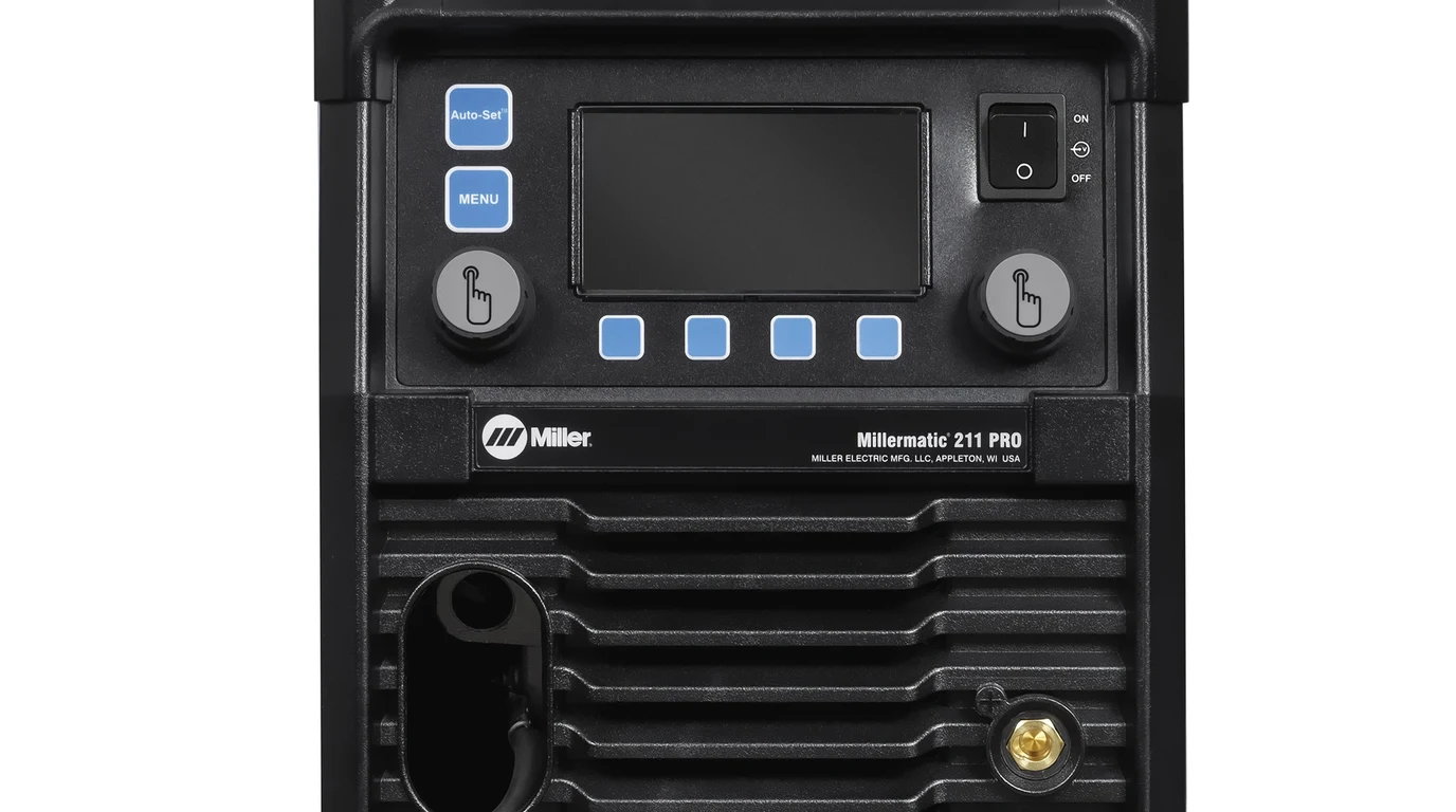
Modern digital multi-process welders (such as the Miller Multimatic 215, ESAB Rebel EMP 215ic, or PrimeWeld MIG180) have replaced heavy transformers with high-speed switching semiconductors:
- High-Frequency Inversion: Incoming 120V or 240V AC utility power is immediately rectified into high-voltage DC and then chopped by Insulated Gate Bipolar Transistors (IGBTs) at frequencies between 20,000 Hz and 100,000 Hz.
- Micro-Transformer Efficiency: Operating at high frequencies allows the magnetic transformer core to shrink from fifty pounds of copper iron down to a ferrite donut smaller than a coffee cup.
- Active Power Factor Correction (PFC): Premium inverter welders incorporate an active PFC boost converter stage. This circuitry continuously aligns incoming AC voltage and current waveforms into phase, maintaining a power factor of 0.95 to 0.99.
- Clean Real-Power Draw: A digital PFC welder producing 140 Amps at the puddle draws only 3,000 to 3,200 Watts of real power, presenting an almost purely resistive load to the solar inverter.
+-----------------------------------------------------------------------------------+
|               TRANSFORMER VS DIGITAL INVERTER WELDER COMPARISON                   |
+-----------------------------------------------------------------------------------+
| Metric                   | Transformer Welder (Legacy) | Digital IGBT with PFC    |
+--------------------------+-----------------------------+--------------------------+
| Internal Technology      | 60Hz Laminated Iron Core    | 50kHz IGBT Inverter Stage|
| Physical Machine Weight  | 85 to 130 lbs (38 - 59 kg)  | 25 to 45 lbs (11 - 20 kg)|
| Power Factor (PF)        | 0.50 to 0.65 (Lagging)      | 0.95 to 0.99 (Near Unity)|
| Input Draw at 140A Weld  | 4,800VA to 5,500VA          | 3,100VA to 3,300VA       |
| Arc Strike Inrush Spike  | 4x to 6x Running Amperage   | 1.1x to 1.3x Soft-Start  |
| Solar Inverter Impact    | Severe Voltage Sag / Tripping| Clean, Smooth Modulation |
+--------------------------+-----------------------------+--------------------------+
High-Frequency TIG Arc Ignition: Why HF Spikes Destroy Solar Inverters
While MIG and Stick welding present primarily current-surge challenges, Gas Tungsten Arc Welding (GTAW / TIG) introduces a dangerous electrical phenomenon: High-Frequency High-Voltage Arc Ignition.
High-Frequency Radiated EMI vs Conducted Gate Spikes
To weld aluminum or stainless steel without touching the tungsten electrode to the workpiece, high-end TIG welders utilize an internal spark-gap oscillator or solid-state pulse generator:
- The welder superimposes a high-voltage (3,000V to 15,000V), high-frequency (several megahertz) electrical burst onto the torch cable.
- This ionizing pulse jumps through the air gap to establish a conductive plasma path, after which the main low-voltage welding power supply engages.
- The Hazard to Solar Inverters: High-frequency radio frequency energy does not stay confined to the welding torch. It radiates into the air as intense Electromagnetic Interference (EMI) and travels backward down the AC power cord as extreme transient voltage spikes ().
- In transformerless high-frequency solar inverters (such as budget off-grid all-in-one units), sensitive digital microprocessor control boards and gate-source junctions of power MOSFETs sit in close capacitive proximity to the AC output bus.
- A single burst of unfiltered HF ignition energy can punch through the gate oxide layer of an inverter’s output transistors, causing immediate silicon puncture and total catastrophic inverter failure.
+-----------------------------------------------------------------------------------+
|                     HOW HIGH-FREQUENCY TIG THREATENS INVERTERS                    |
+-----------------------------------------------------------------------------------+
|  TIG Machine HF Spark Generator (3,000V - 15,000V Pulse at 2MHz to 5MHz)          |
|                                |                                                  |
|       +------------------------+------------------------+                         |
|       |                                                 |                         |
|       v                                                 v                         |
|  Radiated EMI (Airborne RF)                   Conducted Transient Spikes          |
|  • Induces currents in sensor wires           • Traverses AC output cabling       |
|  • Glitches MPPT microcontrollers             • Exceeds MOSFET gate breakdown     |
|  • Freezes inverter LCD displays              • Blown H-bridge switching FETs     |
+-----------------------------------------------------------------------------------+
Safe TIG Arc Striking: Lift-Arc Mode and External Line Filters
To safely weld TIG in an off-grid solar facility:
- Use Lift-Arc Mode: Disable the high-frequency starter switch on your welder and switch the process selector to Lift-TIG (or Lift-Arc). In this mode, the machine applies a tiny non-arcing sensing current. You touch the tungsten to the work, lift it upwards, and the welder senses the break to smoothly ignite the welding arc with zero high-voltage RF discharge.
- Direct Workpiece Grounding: Ensure your welding table is grounded directly to an isolated copper earth ground rod rather than sharing the residential AC green equipment grounding conductor.
- Install an Industrial EMI/RFI Line Filter: If high-frequency AC TIG is mandatory for precision aluminum fabrication, install a heavy two-stage EMI filter (such as a Corcom or Schaffner 30A to 50A power line filter) in a metal enclosure immediately before the welder’s AC wall receptacle.
Sizing Inverter Continuous Watts, Surge Headroom, and Battery C-Rate
To reliably size an off-grid power plant for workshop fabrication, we must translate welding arc output parameters into real DC battery drain.
Calculating Electrical Draw from Welding Arc Parameters
The actual power delivered across the electric arc is governed by basic DC electric law:
For typical Short-Circuit MIG welding of mild steel using 75/25 Ar/CO2 shielding gas:
- Welding Current (): 160 Amperes
- Arc Voltage (): 20 Volts
- Net Arc Power:
To calculate the power demanded from the solar inverter AC output, we must factor in welder power conversion efficiency () and power factor ( for digital inverter):
Factoring in a typical solar inverter conversion efficiency of 92%, the DC battery power draw equals:
+-----------------------------------------------------------------------------------+
|               ELECTRICAL POWER CASCADE FOR A 160A MIG WELDING ARC                 |
+-----------------------------------------------------------------------------------+
|  Welding Puddle Demand: 160A at 20V DC                       = 3,200 Watts       |
|  Welder Conversion Loss (85% IGBT efficiency)                = +565 Watts        |
|  Inverter AC Output Requirement                              = 3,765 Watts (16A) |
|  Inverter Conversion Loss (92% DC-to-AC efficiency)          = +327 Watts        |
|  Net Battery Bank Draw (at nominal 51.2V DC)                 = 4,092 Watts (80A) |
+-----------------------------------------------------------------------------------+
Battery Bank Discharge Amperage and Voltage Sag Under Arc Strike
Drawing 4,092 Watts from a 48V nominal LiFePO4 battery bank requires continuous discharge current:
While an 80A continuous load is modest for a typical 48V 100Ah server rack battery (rated for 100A continuous), the arc strike transient briefly pulls 120A to 140A.
If a battery bank consists of only a single 100Ah battery pack with high internal resistance (), that instantaneous current spike produces a terminal voltage drop:
If the battery is sitting at 50% state of charge (51.5V), a 2.8V drop drags pack voltage down to 48.7V. Under colder garage conditions, internal cell resistance doubles, causing pack voltage to dip beneath the inverter’s low-voltage alarm or trigger BMS overcurrent disconnect.
Engineering Best Practice: Maintain a minimum battery capacity of 200Ah to 300Ah at 48V (10kWh to 15kWh) for any off-grid workshop running arc welders. Paralleling two to three battery modules distributes the 140A arc strike surge down to a gentle 45A per pack, preventing bus voltage fluctuation.
Plasma Cutting on Solar: The Dual-Load Reality of Arc and Air Compressor
Plasma cutting introduces a far more challenging electrical duty cycle than standard welding because it involves two completely separate, simultaneous high-load appliances.

Compressor Inrush Sequencing and Air Dryer Integration
A plasma torch cannot operate without a continuous supply of dry, compressed air at 90 to 110 PSI:
- The Plasma Torch Load: A 45A plasma cutter (such as a Hypertherm Powermax 45XP) operating at full capacity pushes an arc voltage of 130V to 150V DC across the pilot arc: At 85% machine efficiency, the plasma cutter draws 5,800 to 7,100 Watts (24A to 30A at 240V) continuously while cutting half-inch plate steel.
- The Air Compressor Load: Supplying the required 6.0 CFM at 90 PSI requires a 3HP to 5HP air compressor. A standard 3HP single-phase 240V induction motor draws 3,000 Watts running, but requires an instantaneous Locked Rotor Amperage () surge of 45 to 60 Amps (10,800 to 14,400 Watts) every time its pressure switch kicks on!
- The Collision: If the air compressor motor starts up while the operator is actively holding the plasma torch trigger, the combined instantaneous surge will easily exceed 18,000 to 20,000 Watts.
+-----------------------------------------------------------------------------------+
|               PLASMA CUTTING WORST-CASE LOAD COLLISION BENCHMARK                  |
+-----------------------------------------------------------------------------------+
| Component                | Steady Running Power | Peak Simultaneous Surge         |
+--------------------------+----------------------+---------------------------------+
| Hypertherm 45A Plasma    | 6,200 Watts          | 7,200 Watts (Arc strike)        |
| 3HP Air Compressor Motor | 2,800 Watts          | 12,500 Watts (Motor start LRA)  |
| Refrigerated Air Dryer   | 450 Watts            | 900 Watts (Compressor kick)     |
+--------------------------+----------------------+---------------------------------+
| Total Combined Load      | 9,450 Watts          | 20,600 Watts (Overload Trigger) |
+--------------------------+----------------------+---------------------------------+
Preventing Inverter Overload When Plasma Cutting
To operate a plasma cutter reliably without tripping an 8kW to 12kW off-grid inverter:
- Pre-Charge the Air Tank: Before initiating a long cutting sequence, allow the air compressor to run up to full cutoff pressure (150 PSI) and turn off.
- Large Receiver Volume: Adding an auxiliary 30-gallon or 60-gallon receiver tank provides enough air volume to complete several feet of cutting without the compressor motor cycling on during arc time.
- Install a Soft-Starter on the Compressor: Equipping the shop air compressor with an electronic soft starter (such as a Hyper Engineering or Micro-Air soft starter) cuts compressor motor starting surge by 65%, reducing starting inrush from 55A down to under 20A.
Inverter Architecture Selection: Low-Frequency Toroidal vs High-Frequency Transformerless
When designing an off-grid power system intended for regular workshop fabrication, inverter architecture determines long-term hardware survival.
Low-Frequency Inverters: The Inductive Iron Muscle
Low-frequency inverters (such as the Victron Quattro 48/10000 or Schneider Conext XW Pro 6848) utilize a massive toroidal iron-core transformer operating at line frequency (60Hz):
- Massive Thermal Inertia: The huge iron core acts as an electromagnetic flywheel, naturally soaking up sudden inductive current spikes, arc strike dead-shorts, and motor locked-rotor surges without silicon stress.
- Continuous 200% Surge Rating: These units can deliver twice their continuous nameplate rating for twenty to thirty continuous seconds. A 10kVA Victron Quattro can surge to 20,000 Watts to easily absorb a welder strike.
- Natural Filtering: The physical iron core provides high inductive isolation against radiated radio-frequency harmonics and voltage spikes, shielding internal control boards.
High-Frequency Inverters: Clean Efficiency with Fast Semiconductor Trips
Modern all-in-one high-frequency hybrid inverters (such as the Sol-Ark 15K, EG4 18kPV, or Deye 12kW) use high-speed MOSFET/IGBT switching banks and micro-ferrite transformers:
- Superior Weight and Idle Draw: They weigh one-third as much as low-frequency giants and consume only 40W to 60W of idle standby power.
- Digital Overcurrent Protection: Because high-frequency silicon switches cannot tolerate heat buildup, their firmware features lightning-fast electronic current trip limits (often shutting down within tens of milliseconds if current exceeds thresholds).
- Sizing Requirement: To reliably run a 200A welder or plasma cutter on a high-frequency hybrid inverter, the inverter must be rated for at least 12,000W to 15,000W continuous output (e.g., Sol-Ark 15K or EG4 18kPV). At this capacity, a 4,500W welding arc represents less than 35% of the inverter’s continuous threshold, keeping the surge well below fast-trip triggers.
Generator Parallel Assist and Hybrid System Configuration
For off-grid homesteaders operating smaller inverters (5kW to 8kW), running a heavy 240V welder or plasma cutter can exceed system capacity. Rather than replacing the entire inverter system, modern hybrid platforms support Generator Parallel PowerAssist:
+-----------------------------------------------------------------------------------+
|               GENERATOR PARALLEL POWERASSIST IN OPERATION                         |
+-----------------------------------------------------------------------------------+
|               5kW Quiet Inverter Generator (Grid / Gen AC Input)                  |
|                                     |                                             |
|                                     v                                             |
|                   [ Victron Quattro / Sol-Ark 15K ]                              |
|                    (Synchronizes Phase & Frequency)                               |
|                                     ^                                             |
|                                     |                                             |
|                      48V 300Ah LiFePO4 Battery Bank                               |
|                                                                                   |
|                                     |                                             |
|                                     v                                             |
|                   COMBINED AC OUTPUT TO WORKSHOP SUBPANEL                         |
|                    5,000W Generator + 6,000W Inverter Battery Assist               |
|                    = 11,000W Total Continuous Fabrication Power                   |
+-----------------------------------------------------------------------------------+
In this architecture:
- A modest 5,000W inverter generator (such as a Honda EU7000is or Predator 5000) connects to the inverter’s AC generator input terminals.
- The hybrid inverter dynamically locks onto the generator’s AC sine wave frequency and voltage.
- When you strike a 200A welding arc demanding 8,500 Watts, the inverter draws the first 4,500 Watts from the generator up to its programmed current limit.
- The remaining 4,000 Watts is simultaneously supplied from the 48V battery bank via the inverter’s bidirectional switching bridge.
- Once the weld puddle is finished, the generator continues running at steady partial load to gently recharge the battery bank.
This eliminates the need to run an oversized 15kW industrial generator just to handle five minutes of welding.
Practical Rules for Safe Off-Grid Welding
To safeguard your off-grid investment and ensure high-quality welds, follow this checklist before striking an arc:
+-----------------------------------------------------------------------------------+
|                     WORKSHOP FABRICATION SAFETY CHECKLIST                         |
+-----------------------------------------------------------------------------------+
| [X] Welder Selection: Digital IGBT inverter model with Active Power Factor        |
|     Correction (PFC). Retire legacy iron transformer machines from solar power.   |
|                                                                                   |
| [X] Ground Clamp Placement: Clamp directly onto the workpiece, within inches of   |
|     the weld seam. NEVER allow welding return currents to traverse building steel,|
|     electrical conduit, or solar array ground wires.                              |
|                                                                                   |
| [X] TIG Operation: Use Lift-Arc or Scratch-Start mode. If High-Frequency (HF) AC  |
|     TIG is required, install an inline two-stage EMI/RFI power line filter.       |
|                                                                                   |
| [X] Battery Bank Capacity: Minimum 200Ah to 300Ah at 48V (LiFePO4) with low-     |
|     resistance Class T fusing to absorb arc strike current transients.            |
|                                                                                   |
| [X] Air Compressor Staggering: Ensure air tanks are pressurized before firing     |
|     a plasma torch to prevent simultaneous motor LRA and plasma arc inrush.       |
+-----------------------------------------------------------------------------------+
By pairing modern digital welding machines with properly sized split-phase solar inverters and low-impedance LiFePO4 battery storage, remote homesteaders and professional fabricators can operate full metalworking shops entirely free from utility grid reliance.
