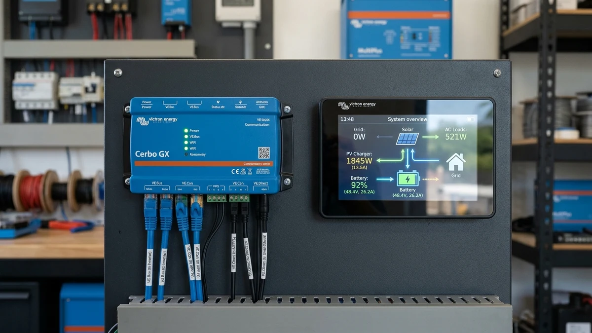
In modern off-grid, marine, and commercial energy storage systems, the inverter-charger and solar charge controllers are merely power-conversion muscle. The brain orchestrating the entire microgrid is the Victron Cerbo GX.
Running Victron’s purpose-built Venus OS Linux operating system, the Cerbo GX aggregates real-time data streams across proprietary communication buses, closed-loop battery networks, digital switches, temperature probes, and tank sensors.
Paired with the sleek, waterproof GX Touch 50 (5-inch) or GX Touch 70 (7-inch) touchscreen display, it delivers instant visibility into system power flows while bridging your local installation to the cloud via the Victron Remote Management (VRM) portal.
However, integrating dozens of disparate hardware protocols into a single compact hub frequently trips up installers. Mismatched termination resistors, improper DC power fusing, or plugging an Ethernet cable into a VE.Bus port can paralyze communication across the entire power wall.
In this comprehensive engineering manual, we provide a complete architectural breakdown of the Cerbo GX, step-by-step wiring instructions, VRM portal configuration, generator auto-start programming, and the best telemetry sensor upgrades to maximize system reliability.
The Cerbo GX accepts an ultra-wide 8V to 70V DC power input, allowing direct connection to 12V, 24V, or 48V battery banks with zero step-down converters. Always install the included blue VE.Can termination plugs in unused CAN ports, and never connect computer LAN cables to VE.Bus ports. VRM enables two-way remote console access worldwide with zero port forwarding required.
Read Closed-Loop BMS Guide →
Cerbo GX Architecture: Ports, Buses, and Sensor Inputs
The bottom and top terminal bays of the Cerbo GX house an extraordinary density of industrial communication interfaces. Understanding the purpose and constraints of each port prevents costly wiring mistakes.
VE.Direct, VE.Bus & CAN Ports
- 3x VE.Direct:Optically isolated 4-pin serial ports for SmartSolar MPPTs, SmartShunt, and BMV-712 battery monitors.
- 2x VE.Bus (RJ45):Dedicated communication bus for MultiPlus, Quattro, and EasySolar inverters. Uses standard Cat5e/6 cables (non-Ethernet).
- 2x VE.Can (RJ45):Dual independent CAN controllers. Port 1 is VE.Can (NMEA 2000 at 250kbps); Port 2 is BMS-Can for managed lithium batteries.
Tanks, Temps, and Relays
- 4x Tank Inputs:Resistive sender inputs configurable for European (0–180Ω) or US standard (240–33Ω) fuel and fresh/grey water tanks.
- 4x Temp Inputs:Micro-voltage sensor inputs calibrated for Victron ASS000001000 temperature probes (battery banks or cold-room monitoring).
- 2x Relays (NO/NC):Dry contact relays rated at 6A 250V AC / 30V DC. Relay 1 is optimized for auto-starting generators; Relay 2 handles custom alerts.
USB Ports and Display Interfaces
The Cerbo GX features three USB-A ports on its top edge:
- USB Port 1 (Display Power): Supplies dedicated power to the GX Touch display.
- USB Ports 2 & 3: Support third-party accessories including RS485-to-USB adapters (for Carlo Gavazzi grid meters), USB GPS antennas, or USB Wi-Fi dongles for long-range external antennas.
- HDMI Output: Transmits pure digital video directly to the GX Touch 50 or GX Touch 70 display panel.
Physical Wiring & Power Supply Installation
Wiring a Cerbo GX is straightforward, but adhering to clean wiring practices ensures zero data packet corruption and protects sensitive electronics against transient spikes.
DC Power Supply Wiring (8V to 70V DC)
The Cerbo GX is powered via a removable green spring-terminal block located on the bottom left. It accepts any DC voltage between and DC.
Power Connection Best Practices
Direct Battery Busbar Connection: Wire the positive lead to the main 12V, 24V, or 48V DC positive distribution busbar (such as a Victron Lynx Distributor). Do not power the Cerbo GX from an auxiliary 12V automotive socket or downstream DC branch that turns off when the inverter sleeps.
Inline Overcurrent Protection: Victron supplies an inline glass fuse holder with a 3.15A slow-blow fuse pre-crimped on the positive power wire. Never bypass this fuse; it protects the Cerbo’s internal DC-DC converter against catastrophic short circuits.
Ground Reference: Wire the negative lead directly to the negative DC busbar or battery shunt load side.
Installing the GX Touch 50 / GX Touch 70 Display
The GX Touch display is a capacitive touchscreen designed for flush wall mounting or surface mounting on electrical cabinets:
- Use the included drilling template to cut a single circular hole () in your panel.
- Feed the dual-headed cable through the cutout. The single cable splits cleanly into an HDMI connector and a USB-A power plug.
- Secure the display bracket using the four mounting screws, then snap the GX Touch front bezel securely into place. The silicone seal achieves an IP54 splashproof rating, making it suitable for marine cockpits and humid outdoor utility closets.
- Plug the HDMI connector into the HDMI port on the Cerbo GX, and plug the USB connector into the adjacent dedicated USB display port.
The Critical VE.Can Termination Resistor Rule
CAN bus networks require exactly two termination resistors—one at each physical end of the daisy chain—to absorb signal reflections ().
- Every Cerbo GX comes packaged with two small blue RJ45 terminators.
- If you have a SmartSolar MPPT wired into the VE.Can port, insert one blue terminator into the spare VE.Can port on the Cerbo GX, and the second terminator into the final device on the chain.
- Failure Symptom: If terminators are omitted, the Cerbo GX will intermittently drop communication, showing missing MPPTs or displaying corrupted telemetry graphs on the GX Touch.
Networking and Internet Connectivity Configuration
To enable remote telemetry, software updates, and notifications, the Cerbo GX must connect to a local area network (LAN).
Gigabit Ethernet (LAN)
Hardwired shielded Cat6 cable plugged directly into the RJ45 Ethernet port. Provides 100% immune, zero-latency telemetry logging unaffected by Wi-Fi reboots or interference.
Internal 2.4GHz Wi-Fi
Connects to residential routers or mobile Starlink hotspots. During commissioning, the Cerbo GX broadcasts its own Wi-Fi Access Point (SSID: Venus-GX-…) for initial setup via smartphone.
GX LTE 4G Cellular Modem
An optional USB cellular modem housing a standard SIM card. Features built-in GPS tracking for mobile RVs, expedition overland rigs, and workboats with automatic geo-fencing alarms.
Victron Remote Management (VRM) Portal Integration
The Victron Remote Management (VRM) portal is universally regarded as the gold standard of cloud energy telemetry. It is completely free with no recurring subscription fees.
Step-by-Step VRM Onboarding
Retrieve Your VRM Portal ID
On the GX Touch display, tap Settings → VRM online portal → VRM Portal ID. The ID is a 12-character alphanumeric code matching the Cerbo’s primary MAC address (e.g. b827eb12a45c). It is also printed on the physical barcode sticker underneath the unit.
Link System to Victron VRM Account
Navigate to vrm.victronenergy.com on your computer or mobile app. Create an account, click Add Installation, select Cerbo GX, and input your 12-character VRM Portal ID. Within 60 seconds, historical charts and live system telemetry will populate.
Enable Two-Way Remote Console
Under Settings → Remote Console, toggle Enable on VRM to ON. This establishes a secure encrypted outbound tunnel. You can now view and touch the exact GX Touch screen interface from any browser on earth—allowing remote configuration of inverter thresholds, generator testing, and software updates.
Advanced Automation: Generator Auto-Start & Dynamic ESS Rules
Beyond passive monitoring, the Cerbo GX acts as a programmable automation controller.
Two-Wire Generator Auto-Start Programming
By wiring Relay 1 (dry contact terminals NO and COM) to the remote-start input of a dual-fuel inverter generator (such as a Champion, Cummins Onan, or Westinghouse), Venus OS can start and stop the generator autonomously.
Under Settings → Generator start/stop → Conditions, configure multi-parameter trigger rules:
- State of Charge (SoC) Rule: Start generator when Battery SoC falls to ; stop generator when SoC reaches .
- High AC Inverter Load Rule: If an air conditioner or electric oven pulls over for more than 30 seconds, start the generator immediately to assist the Victron MultiPlus-II via PowerAssist.
- Quiet Hours Enforcement: Set Quiet Hours between 10:00 PM and 7:00 AM. During quiet hours, generator startup is blocked unless battery voltage drops to an emergency threshold ( on a 48V pack).
- Periodic Test Runs: Program the Cerbo to start the generator for 15 minutes on the first Sunday of every month to exercise the engine and circulate lubricating oil.
Dynamic ESS: Real-Time Energy Market Arbitrage
For grid-tied installations with time-of-use (TOU) or dynamic spot-market pricing (such as Nord Pool, Amber Electric, or Tibber), Venus OS v3.x includes native Dynamic ESS:
- The Cerbo GX downloads next-day hourly energy prices via your internet connection.
- It cross-references your historical consumption patterns and predicted solar solar irradiance from satellite weather models.
- Autonomous Execution: When grid electricity drops to cheap or negative prices, the Cerbo charges your batteries from the grid at maximum speed. During peak afternoon rate spikes, it discharges the batteries to cover home loads, cutting grid electricity costs by up to 60%.
Recommended Telemetry Sensors & Upgrades
To exploit the full analytical power of Venus OS, integrate these plug-and-play sensor expansions:
| Telemetry Hardware | Connection Interface | Primary Function | Ideal Application |
|---|---|---|---|
| RuuviTag Pro Sensor | Bluetooth Low Energy (BLE) | Wireless ambient temperature, humidity & air pressure | Battery compartment & refrigerator monitoring |
| Victron ASS000001000 | Analog Temp Input | Hardwired thermal lug bolted directly to battery negative post | Accurate thermal compensation for lead-acid/LFP |
| Carlo Gavazzi EM24 / ET112 | RS485-to-USB Cable | High-speed revenue-grade grid import/export metering | Dynamic ESS and whole-home power measurement |
| KUS / WEMA Tank Senders | Analog Tank Input (0–180Ω) | Fuel, fresh water, and black water level telemetry | RV, campervan, and marine yacht tank monitoring |
| Victron GX LTE 4G Modem | USB Port + External Antenna | Independent cellular internet uplink & GPS tracking | Off-grid cabins without Starlink; mobile RV security |
Cerbo GX Telemetry Diagnostic Matrix
Use this quick-reference engineering table to diagnose communication and telemetry faults:
| Observed Symptom | Probable Cause | Physical Diagnostic Check | Engineering Solution |
|---|---|---|---|
| GX Touch screen remains totally black | Insufficient USB power or bad HDMI seat | Check if Cerbo green power LED is solid; reseat HDMI | Ensure USB plug is in Display USB port; check 3.15A inline fuse. |
| Missing VE.Can MPPTs or Battery on display | Missing 120Ω bus termination | Measure resistance across CAN-H/L with power OFF ( expected) | Insert blue RJ45 termination plug into spare VE.Can port. |
| VE.Bus Error 17 / Inverter Comm Lost | Damaged cable or plugged into LAN port | Verify cable is in VE.Bus port, not Ethernet LAN | Inspect RJ45 cable for crushed pins; replace with genuine Cat6 patch cord. |
| VRM shows “Last Seen 3 Hours Ago” | DNS failure or local Wi-Fi router drop | Check Settings → Wi-Fi → IP Address | Assign a static local IP and set DNS to 1.1.1.1 / 8.8.8.8. |
| Tank sensor reads erratic 0% / 100% jumping | Open circuit or incorrect Ohm standard | Measure resistance of disconnected sender leads with multimeter | Set tank input standard to match sensor (European 0–180Ω vs US 240–33Ω). |
Frequently Asked Questions
Can the Cerbo GX operate without an internet connection?
Yes. The Cerbo GX is a fully standalone industrial controller. All local power flows, generator auto-start rules, cell balancing logic, and touchscreen displays function perfectly with zero internet connectivity. It caches up to 6 months of telemetry internally and uploads historical data the moment a Wi-Fi or cellular network is restored.
What is the difference between Venus OS and Venus OS Large?
Venus OS Large is an official advanced firmware release that includes Node-RED and Signal K pre-installed. It allows custom low-code automation scripting—such as automatically turning on water heaters when solar production exceeds or sending custom Telegram/Discord notifications during low-battery events.
Can I connect non-Victron batteries (like EG4 or Pylontech) to the Cerbo GX?
Yes. Managed lithium batteries communicating via the Pylontech CAN protocol connect directly into the Cerbo’s BMS-Can port using a Type B RJ45 cable. The Cerbo automatically reads individual cell voltages, temperature alarms, and State of Charge.
How many VE.Direct devices can I connect if I run out of ports?
The Cerbo GX has three built-in VE.Direct ports. If you have four or more MPPTs and shunts, you can plug in additional devices using standard VE.Direct-to-USB adapter cables (Victron part ASS030530010) into the Cerbo’s spare USB ports or through a powered USB hub.