Few events disrupt an off-grid homestead or remote agricultural operation more abruptly than an inverter tripping into fault lockout the exact millisecond the well pump pressure switch closes.
In a conventional grid-tied home, the massive short-circuit current capacity of utility grid power can often mask subtle mechanical friction, degraded motor windings, or borderline start capacitors. A utility grid transformer easily supplies 100 to 200 Amperes of instantaneous inductive surge current without flinching.
However, off-grid split-phase inverters and hybrid solar power plants—including modern high-frequency transformerless units like the EG4 6000XP or Growatt SPF 5000ES—are governed by hyper-sensitive, microsecond-fast digital signal processors (DSPs). If the pump motor draws an instantaneous inductive surge spike exceeding the inverter’s peak silicon limit, or if sub-surface motor windings leak even a few milliamperes of current into the well casing groundwater, the inverter instantly shuts down on Overcurrent (OC) or Ground Fault (GFDI/RCD) protection.
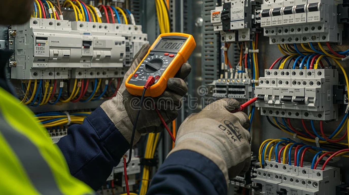
Diagnosing why a deep well pump trips an off-grid inverter requires a disciplined, systematic electrical troubleshooting process. Rather than guessing or needlessly pulling hundreds of feet of heavy drop pipe out of the borehole casing, technicians must use calibrated test instruments—specifically a digital multimeter (DMM), an insulation resistance tester (Megohmmeter), and a clamp meter—to isolate the failure above ground.
Root Causes of Off-Grid Inverter Trips on Deep Well Pumps
Deep well submersible pumps present one of the most demanding electrical loads in residential and agricultural engineering. Submerged hundreds of feet underwater, a single-phase induction motor must overcome intense mechanical and hydraulic inertia while operating inside a liquid dielectric environment.
+-----------------------------------------------------------------------------------+
|                        OFF-GRID INVERTER TRIP TAXONOMY                            |
+-----------------------------------------------------------------------------------+
|                                                                                   |
|  [ Instantaneous Overcurrent ]       [ Ground Fault (RCD/GFDI) ]     [ DC Bus Sag ]
|  • Locked Rotor Amps (LRA) surge    • Underwater splice leakage      • High internal battery IR
|  • Sand/scale bound pump wet-end    • Motor stator winding puncture  • Under-gauged DC cables
|  • Failed control box start cap     • Blown surge arrestor to ground • BMS high-current cutoff
|  • Welded potential relay contacts  • Chafed drop-cable on casing    • Cold LiFePO4 cell sag
|                                                                                   |
+-----------------------------------------------------------------------------------+
When an off-grid inverter shuts down during pump cycling, the root failure originates from one of four primary mechanisms:
- Locked Rotor Amps (LRA) Inductive Surge: At the exact millisecond of startup (), an AC induction motor draws between 5 to 7 times its full-load running amperage (FLA). On high-frequency inverters with limited surge buffers, this current spike exceeds hardware limits before the rotor breaks static friction.
- Insulation Degradation and Groundwater Leakage: Submersible drop cables (typically twisted 12/3 or 10/3 submersible wire) and heat-shrink splices vibrate against the steel or PVC well casing. Over years of torque-twist cycles, microscopic abrasions allow water to penetrate, creating a high-resistance ground fault.
- Control Box Component Failure: In 3-wire pump systems, the above-ground control box contains a start capacitor, a run capacitor, and a potential relay. If the starting capacitor ruptures or the relay contacts weld shut, the start winding remains energized continuously, causing massive overcurrent.
- Inverter DC Bus Voltage Collapse: A high AC surge draw demands hundreds of DC Amperes from the battery bank. If the battery bank has high internal resistance, cold LiFePO4 cells, or inadequate 4/0 AWG battery cabling, the DC voltage drops below the inverter’s low-voltage cutoff threshold ( on a 48V nominal system).
Systematic Fault Isolation: Overcurrent vs Ground Fault vs DC Bus Sag
Before picking up hand tools or opening the wellhead seal, you must identify which protective threshold is triggering the inverter shutdown. Every quality solar inverter records specific numerical error codes in its event log.
Diagnostic Verification Protocol
Follow this three-step isolation sequence to categorize the trip:
[ Inverter Trips on Pump Startup ]
               |
               v
    Check Inverter Fault Log
               |
    +----------+--------------------+
    |                               |
[ Fault: Ground Fault / RCD ]   [ Fault: Overcurrent / Hardware Surge ]
    |                               |
    v                               v
Disconnect Pump Cable from      Disconnect Pump Cable from
Inverter AC Output. Reset.      Inverter AC Output. Reset.
    |                               |
    +-> Still Trips: Inverter Fault  +-> Still Trips: Inverter Fault
    +-> Clears: Cable/Motor Ground  +-> Clears: Check Startup Surge
                                         |
                                         v
                                  Check Battery DC Voltage
                                  During Startup Attempt
                                         |
                                         +-> DC Drops >6V: Battery Sag
                                         +-> DC Holds Steady: Motor LRA / Control Box
Distinguishing Electrical Symptoms
- Overcurrent (Code: F01, OC, Inverter Hardware Overload): The inverter trips within 50 to 500 milliseconds of contactor closure. The lights in the cabin or workshop may dim sharply right before the trip. This indicates excessive inductive inrush, a locked pump impeller, or an open start winding circuit.
- Ground Fault (Code: F08, GFDI, Earth Leakage, Residual Current >30mA): The inverter trips instantly upon relay engagement. The DC battery bus voltage does not sag. This occurs because phase current is leaking through compromised motor insulation into the earth ground path rather than returning through neutral or the opposing phase.
- Low DC Bus Voltage (Code: F03, Low Battery Voltage Sag): The inverter shuts down not because of AC line limits, but because battery terminal voltage dipped below minimum operating levels during motor acceleration.
Testing Motor Insulation Resistance with a Megohmmeter
Standard digital multimeters apply only 3 to 9 volts DC across their test leads when measuring resistance. While a standard DMM is sufficient for checking continuity, it cannot detect high-voltage insulation breakdown under water pressure. Submerged well pumps operate at 120V to 240V AC, producing peak electrical potentials exceeding 340 volts ().
To detect water seepage through micro-fractures in motor winding enamel or subterranean cable splices, technicians must use a Megohmmeter (Megger) capable of injecting a calibrated 500V or 1,000V DC test potential.
+-----------------------------------------------------------------------------------+
|                        MEGOHMMETER BENCHMARK MATRIX                               |
+-----------------------------------------------------------------------------------+
|  Insulation Resistance Reading  |  Condition & Operational Status                 |
+---------------------------------+-------------------------------------------------+
|  > 100 Megohms (100 MΩ)         |  Brand new motor and newly installed drop cable |
|  20 Megohms – 100 Megohms       |  Healthy submerged installation in normal service|
|  1 Megohm – 20 Megohms          |  Degraded insulation; splice moisture ingress   |
|  0.5 Megohm – 1 Megohm          |  Severe degradation; will trip sensitive RCD/GFCI|
|  < 0.5 Megohms (0.5 MΩ)         |  Dead short to ground; motor or cable failure   |
+-----------------------------------------------------------------------------------+
Performing the Submersible Insulation Test
Always isolate and discharge circuits before connecting high-voltage insulation test instruments:
- Lock Out Electrical Power: Open the main AC disconnect switch feeding the well pump control box. Verify zero AC voltage between all conductors using a calibrated True-RMS multimeter.
- Disconnect Motor Conductors: Disconnect all drop-cable conductors (typically Red, Black, Yellow, and bare/green Ground) from the control box or pressure switch terminals. The test must isolate the down-hole wire and motor from above-ground electronic components.
- Connect Ground Reference: Clamp the negative (Earth/Return) lead of the megohmmeter directly to the metal well casing, the electrical service grounding electrode, or the bare copper ground wire running down the hole.
- Apply 500V DC Test Potential: Attach the positive (Line) test probe to one of the motor power leads (e.g., Black). Initiate the test for a continuous 60-second duration to allow capacitive absorption current to stabilize.
- Analyze Resistance Values: Repeat the test across all power conductors (Red to Ground, Yellow to Ground, Black to Ground). Because the windings are connected internally inside the motor stator, healthy conductors will exhibit virtually identical insulation values to earth ground.
If the test measures below 0.5 Megohms, moisture has entered the system. To determine whether the failure is in the drop cable splice or inside the down-hole motor stator, the drop wire must be disconnected at the wellhead pitless adapter and measured separately.
Measuring 3-Wire Submersible Motor Winding Resistances
Deep well submersible pump motors fall into two primary mechanical architectures: 2-Wire Motors (which incorporate an internal centrifugal switch and start capacitor sealed inside the down-hole motor shell) and 3-Wire Motors (which route individual phase and start leads up to a surface-mounted control box).
In off-grid solar systems, 3-wire pumps are strongly preferred because all starting capacitors and potential relays reside above ground in a serviceable enclosure.
       +---------------------------------------------+
       |   3-WIRE SUBMERSIBLE MOTOR WINDING CIRCUIT   |
       +---------------------------------------------+

                         YELLOW (Common)
                                o
                               / \
                              /   \
                 R_main      /     \    R_start
             (Low Resistance)/       \ (High Resistance)
                            /         \
                           /           \
                          o             o
                     BLACK (Main)    RED (Start)
                          \             /
                           \           /
                            \         /
                             +-------+
                              R_total = R_main + R_start
The Fundamental Winding Formula
On any 3-wire single-phase motor (such as Franklin Electric, Grundfos, or Pentair), the stator contains two distinct sets of insulated copper windings:
- Main Run Winding (Black to Yellow): Heavy-gauge magnet wire designed to carry continuous running current. Offers low electrical resistance ().
- Auxiliary Start Winding (Red to Yellow): Finer-gauge copper wire designed to produce high starting torque during the initial 300 milliseconds. Offers substantially higher resistance ().
The mathematical relationship across the three drop-cable conductors must always satisfy Kirchhoff’s resistance loop:
Benchmark Resistance Readings for Standard Motors
| Motor Power Rating (230V Single-Phase) | Main Winding: Black to Yellow | Start Winding: Red to Yellow | Total Across Windings: Black to Red |
|---|---|---|---|
| 0.5 HP (0.37 kW) | 4.2 – 5.2 | 10.5 – 12.5 | 14.7 – 17.7 |
| 0.75 HP (0.55 kW) | 3.0 – 3.8 | 8.0 – 9.8 | 11.0 – 13.6 |
| 1.0 HP (0.75 kW) | 2.2 – 2.8 | 6.5 – 7.8 | 8.7 – 10.6 |
| 1.5 HP (1.10 kW) | 1.5 – 1.9 | 4.5 – 5.5 | 6.0 – 7.4 |
| 2.0 HP (1.50 kW) | 1.1 – 1.4 | 3.2 – 3.9 | 4.3 – 5.3 |
(Note: Add to per 100 feet of #12 or #10 AWG submersible copper drop cable).
Diagnosing Winding Faults from Resistance Data
- Open Circuit ( reading): Indicates a broken drop wire, a disconnected terminal, or a burned-out winding coil inside the motor stator.
- Zero Resistance ( reading): Indicates a dead short circuit between two windings, typically caused by localized overheating melting the winding enamel.
- Unbalanced Resistance (): Indicates an internal winding insulation turn-to-turn short. The motor will draw excessive Locked Rotor Amps and instantly trip high-frequency inverters.
Inspecting Above-Ground Control Boxes: Capacitors and Potential Relays
If the motor windings and insulation resistance test within normal specifications, the root cause of off-grid inverter tripping almost always resides inside the above-ground pump control box (e.g., Franklin Electric QD or Standard Control Box).
+-----------------------------------------------------------------------------------+
|                     PUMP CONTROL BOX INTERNAL SCHEMATIC                           |
+-----------------------------------------------------------------------------------+
|                                                                                   |
|   L1 Line In  o-----+-----------------------------------> Black (Main Run)        |
|                     |                                                             |
|                     |      +--------------------+                                 |
|                     +-----[ Start Capacitor     ]----+                            |
|                            +--------------------+    |                            |
|                                                      |                            |
|                     +--------------------+           |                            |
|   L2 Line In  o-----+ Potential Relay    ]-----------+--> Red (Start Winding)     |
|                     | [Normally Closed]  |                                        |
|                     +--------------------+                                        |
|                                                                                   |
|   Common      o-----------------------------------------> Yellow (Common)         |
|                                                                                   |
+-----------------------------------------------------------------------------------+
Start Capacitor Degradation and Swelling
The electrolytic start capacitor provides the critical 90-degree phase shift required to produce initial rotational torque. These capacitors operate under extreme electrical and thermal stress:
- Visual Inspection: Inspect the top rubber pressure-relief plug and the bottom of the black phenolic cylinder. If the rubber plug is bulged, torn, or leaking oily electrolyte (dielectric fluid), the capacitor has suffered severe internal breakdown.
- Capacitance Verification with a DMM: Using a digital multimeter equipped with a capacitance measurement mode (), discharge the capacitor using a 20k-ohm resistor, disconnect both terminals, and measure the capacitance. A healthy 1.0 HP Franklin start capacitor is typically rated for 86 to 103 . If measured capacitance drops more than 10% below minimum specification, starting torque collapses, motor acceleration stalls, and the inverter trips on locked-rotor overcurrent.
Potential Relay Contact Pitting and Welding
The potential relay is an electro-magnetic switch with normally-closed (NC) heavy-duty contacts. When power is first applied, current flows through the closed contacts into the start winding. As the motor reaches approximately 80% of synchronous speed (within 200–300 ms), the rising back-EMF voltage induced across the start winding energizes the relay coil, opening the contacts and cutting power to the start winding.
- Welded Contacts: If repeated inductive starting arcs have welded the silver contact tips together, the start winding remains energized indefinitely. Within 1 to 2 seconds, the high starting current overheats the system and trips the inverter on overload.
- Burned / Open Contacts: If carbon buildup or arcing prevents the contacts from conducting, zero current reaches the start winding. The motor fails to turn, pulls full Locked Rotor Amps on the main winding alone, and trips the inverter within 100 milliseconds.
Diagnosing Lightning Strikes and Down-Hole Surge Arrestor Failure
Submersible well pumps are exceptionally vulnerable to atmospheric lightning strikes. Because the steel well casing extends hundreds of feet into saturated earth, it acts as a massive lightning rod.
                                      [ Lightning Strike ]
                                               |
                                               v
                                   [ High-Voltage Surge ]
                                               |
                                 +-------------+-------------+
                                 |                           |
                                 v                           v
                      [ Motor Surge Arrestor ]    [ Motor Stator Insulation ]
                                 |                           |
                                 +-------------+-------------+
                                               |
                                               v
                                [ Carbon Conductive Path ]
                                               |
                                               v
                          [ Inverter GFDI/RCD Instant Lockout ]
To protect motors from high-voltage spikes, manufacturers install silicon carbide or metal oxide varistor (MOV) surge arrestors either inside the control box or directly encapsulated into the motor lead shell.
When an arrestor absorbs a lightning strike, it shunts thousands of volts safely into the well casing ground. However, absorbing a direct or near-strike frequently causes the internal varistor discs to shatter or fuse into a permanent conductive path:
- The motor windings may remain mechanically and electrically intact.
- However, the blown surge arrestor now presents a direct 10-ohm to 1,000-ohm short circuit from the line conductors to the grounded motor frame.
- The moment an off-grid inverter engages its output contactor, its sensitive Ground Fault Detection and Interruption (GFDI) or Residual Current Device (RCD) detects current escaping to ground and trips instantly.
To verify a blown down-hole arrestor: disconnect all surface wiring, perform a 500V Megger test to ground. If resistance is near zero but winding resistances between Black, Red, and Yellow are completely normal, the down-hole lightning arrestor has sacrificed itself and shorted to the casing.
Comprehensive Field Diagnostic Reference and Resolution Matrix
Use this systematic engineering matrix to match specific electrical symptoms with proven corrective actions:
| Diagnostic Measurement | Measured Value | Probable Root Cause | Corrective Engineering Action |
|---|---|---|---|
| Insulation Resistance (500V Megger) | Water penetration in drop cable splice or stator burnout | Isolate cable at wellhead; if cable is good, pull pump to replace motor and re-splice with heavy-duty heat shrink. | |
| Insulation Resistance (500V Megger) | Deteriorating wire insulation or failing drop cable | Plan cable replacement; install an isolation transformer if inverter RCD threshold is tripping prematurely. | |
| Winding Resistance () | (Open) | Severed drop conductor or burned stator coil | Check surface connections; test continuity at wellhead pitless adapter to isolate underground broken wire. |
| Start vs Main Resistance | Turn-to-turn internal short in motor stator | Replace submersible motor; internal short pulls destructive LRA and will damage inverter output FETs. | |
| Start Capacitor ( Mode) | below spec | Electrolyte dry-out or thermal venting | Replace start capacitor with exact OEM microfarad and voltage rating; verify bleed resistor is intact. |
| Potential Relay Resistance | across open coil | Shorted relay coil or welded switch contacts | Replace potential relay (e.g., Franklin Electric 111300 series OEM replacement kit). |
| Inverter DC Bus Voltage | Sags on start | Battery internal resistance high or DC cable undersized | Upgrade battery interconnects to 4/0 AWG cables or install a dedicated submersible well pump soft starter. |
| Inverter AC Voltage | Trips on Instant Overcurrent | High startup surge exceeding inverter peak kVA | Retrofit an electronic soft starter, replace high-frequency inverter with a heavy-duty low-frequency model, or install a dedicated solar pump VFD controller. |
Proven Engineering Solutions to Eliminate Inverter Tripping
Once the physical down-hole hardware has been confirmed healthy, resolving persistent nuisance tripping requires addressing the inherent mismatch between inductive AC motor startup dynamics and solid-state inverter surge limitations.
+-----------------------------------------------------------------------------------+
|                        PUMP SURGE SUPPRESSION TOPOLOGIES                          |
+-----------------------------------------------------------------------------------+
|                                                                                   |
|  [ Architecture A: Solid-State Electronic Soft Starter ]                          |
|  • Reduces starting inrush by 65% to 70% (e.g., Micro-Air or Hyper Engineering)   |
|  • Smoothly ramps motor voltage over 300 to 500 milliseconds                      |
|  • Eliminates inverter LRA overcurrent spikes while preserving existing pump      |
|                                                                                   |
|  [ Architecture B: Solar Variable Frequency Drive (VFD) ]                         |
|  • Direct PV-to-Pump conversion with zero battery requirement                     |
|  • Converts single-phase AC or 3-phase motor power with 1.0x starting current     |
|  • Completely bypasses home battery inverter system                               |
|                                                                                   |
|  [ Architecture C: Low-Frequency Toroidal Inverter Upgrade ]                      |
|  • Heavy iron-and-copper transformer absorbs 300% surge for up to 20 seconds      |
|  • Superior inductive load handling compared to lightweight transformerless units |
|                                                                                   |
+-----------------------------------------------------------------------------------+
Retrofitting a Solid-State Electronic Soft Starter
The most cost-effective solution for homesteaders experiencing start-up trips on high-frequency inverters is retrofitting a specialized pump soft starter (such as a Micro-Air EasyStart or a Franklin SubDrive Connect). By employing solid-state phase angle firing, soft starters ramp voltage smoothly over several hundred milliseconds, reducing peak Locked Rotor Amps by 65% to 70%.
A standard 1.0 HP pump drawing 45 Amperes of instantaneous locked-rotor surge can be tamed to draw less than 15 Amperes, allowing even modest 5,000W off-grid inverters to start deep well pumps without light flicker or system tripping.
Transitioning to a Dedicated Solar Pump VFD
For deep boreholes located far from the main dwelling, routing well power through a residential battery inverter is often suboptimal. Modern agricultural installations increasingly deploy dedicated solar pump inverters and VFD controllers. These units connect directly to a dedicated string of high-voltage solar panels, eliminate battery round-trip energy losses, and provide controlled soft-start ramp profiles with zero inrush current spikes.