In off-grid solar systems and hybrid microgrids, the purity of alternating current (AC) electricity is frequently taken for granted. Installers verify that an inverter produces one hundred and twenty volts or two hundred and forty volts at sixty hertz, observe that lights illuminate, and assume power delivery is flawless. Yet behind the illuminated front displays of household appliances and workshop machinery, invisible electrical pollution—known as Total Harmonic Distortion (THD)—silently degrades system efficiency, overheats motors, triggers nuisance ground-fault trips, and destroys sensitive electronics.
While utility grid power typically exhibits pristine, low-distortion sine waves (regularly maintaining voltage THD below two percent), solar inverters must synthesize alternating current from direct current battery banks using high-speed semiconductor switching. Depending on whether an inverter utilizes high-frequency Pulse Width Modulation (PWM) or low-frequency iron-core transformers, its ability to maintain a pure sinusoidal waveform under real-world non-linear loads varies dramatically.
This engineering guide investigates the physics and mathematics of inverter harmonics, quantifies the mechanical and thermal damage caused by odd-order harmonic frequencies in induction motors, benchmarks laboratory oscilloscope and spectrum analyzer measurements, and details proven filtering architectures—including line reactors and tuned LC output networks—to guarantee utility-grade power quality.

Executive Summary: The Physics of Alternating Current Waveform Distortion
An ideal single-phase alternating current electrical source produces a pure sinusoidal voltage waveform described mathematically by:
Where represents the fundamental angular frequency (fifty hertz or sixty hertz). In this pristine mathematical ideal, all electrical energy exists exclusively at the fundamental frequency, yielding zero harmonic distortion ().
In solid-state solar inverters, direct current from a battery bank or photovoltaic array cannot be converted into an alternating sine wave through continuous analog amplification without massive, unacceptable heat loss. Instead, inverters utilize switched-mode power conversion: high-speed power transistors—such as Insulated Gate Bipolar Transistors (IGBTs) or Silicon Carbide (SiC) MOSFETs—slice direct current voltage into tens of thousands of square-wave pulses per second using high-frequency Pulse Width Modulation.
+------------------------------------------------------------------------------------+
|               WAVEFORM TOPOLOGY COMPARISON: HARMONIC PURITY PROFILE                |
+------------------------------------------------------------------------------------+
|  SQUARE WAVE (Primitive Inverters):                                                |
|  - THD Level: 45% to 50% THD                                                       |
|  - High acoustic buzzing, catastrophic motor overheating, destroyed electronics.   |
|                                                                                    |
|  MODIFIED SINE WAVE (Budget Camping Inverters):                                    |
|  - THD Level: 25% to 35% THD                                                       |
|  - Severe odd harmonic spikes (3rd, 5th, 7th), high crest factor, motor hum.       |
|                                                                                    |
|  PURE SINE WAVE (Modern Solar Hybrid Inverters):                                   |
|  - THD Level: Under 3% at linear load; Spikes to 5% - 10% under non-linear loads.  |
|  - Smooth fundamental wave with low-pass filtered switching ripple.                |
+------------------------------------------------------------------------------------+
While passive low-pass LC filters installed across inverter output terminals smooth out the brutal twenty-kilohertz switching carrier frequency, the interaction between inverter internal output impedance and non-linear consumer loads distorts the fundamental voltage wave, introducing parasitic integer multiples of the fundamental frequency known as harmonics.
Mathematical Foundations of Total Harmonic Distortion
To evaluate electrical power quality objectively, electrical engineers rely on Fourier analysis to decompose complex, distorted periodic waveforms into an infinite series of sinusoidal components.
Fourier Series Decomposition and Orthogonal Harmonic Frequencies
According to Fourier’s theorem, any periodic non-sinusoidal voltage waveform with period can be represented as the sum of a direct current component, a fundamental frequency sinusoidal component, and an infinite series of harmonic components:
Where represents the harmonic integer order ( is the fundamental sixty-hertz wave, is one hundred and twenty hertz, is one hundred and eighty hertz, and so forth).
Voltage Total Harmonic Distortion () is defined by IEEE Standard 519 as the ratio of the root-mean-square (RMS) sum of all harmonic voltage components to the RMS magnitude of the fundamental voltage component:
Similarly, Current Total Harmonic Distortion () measures the distortion present in the load current waveform:
In utility-interconnected systems and high-reliability off-grid applications, maintaining voltage THD below five percent is mandatory to prevent equipment malfunction and excessive thermal dissipation.
Odd Harmonics and Negative Sequence Braking Torque
Because solar inverters utilize symmetrical push-pull half-bridge or full-bridge switching topologies, the synthesized alternating current waveforms exhibit half-wave symmetry:
Due to half-wave symmetry, all even-order harmonics () cancel out mathematically. Consequently, power quality distortion in solar inverters is dominated almost entirely by odd-order harmonics:
In three-phase and split-phase power systems, these odd harmonics behave with radically different electromagnetic characteristics:
+------------------------------------------------------------------------------------+
|               HARMONIC ORDER SEQUENCE AND ROTATING FIELD DYNAMICS                  |
+------------------------------------------------------------------------------------+
|  HARMONIC ORDER     SEQUENCE COMPONENT     MOTOR ROTATION EFFECT                   |
+------------------------------------------------------------------------------------+
|  Fundamental (1st)  Positive Sequence (+)  Forward mechanical driving torque       |
|  Third (3rd)        Zero Sequence (0)      Triplen: Circulates in neutral, heating |
|  Fifth (5th)        Negative Sequence (-)  Counter-rotational reverse braking      |
|  Seventh (7th)      Positive Sequence (+)  Forward mechanical torque (turbulent)   |
|  Ninth (9th)        Zero Sequence (0)      Triplen: Neutral conductor overload     |
|  Eleventh (11th)    Negative Sequence (-)  Counter-rotational reverse braking      |
+------------------------------------------------------------------------------------+
The presence of negative sequence harmonics—most notably the fifth harmonic (three hundred hertz in a sixty-hertz system)—is catastrophic for induction motors (such as well pumps, refrigerator compressors, and air conditioner blowers). While the fundamental voltage creates a magnetic stator field rotating forward at eighteen hundred or thirty-six hundred RPM, the fifth harmonic creates a magnetic field rotating in the reverse direction at five times fundamental speed.
This counter-rotating magnetic field produces negative braking torque against the motor rotor. The motor must consume extra fundamental current simply to overcome its own internal electromagnetic counter-torque, transforming valuable solar battery kilowatt-hours into wasted heat.
Inverter Switching Topologies: High-Frequency PWM vs Low-Frequency Iron Core
The physical architecture of a solar inverter fundamentally dictates its harmonic response under dynamic loads:
- High-Frequency Transformerless Inverters (EG4, Sol-Ark, Growatt, SMA): These modern inverters utilize digital signal processors (DSP) to switch silicon MOSFETs at sixteen to forty kilohertz. Output voltage is shaped via software feedback loops, and high-frequency carrier ripple is suppressed using compact ferrite-core LC filters. While highly efficient (ninety-six to ninety-eight percent peak efficiency) and lightweight, their internal output impedance () is non-zero. When non-linear loads draw current in sharp, brief pulses, the voltage across the inverter internal impedance drops proportionally, distorting the output voltage wave.
- Low-Frequency Iron-Core Inverters (Victron MultiPlus, Schneider Conext, MidNite Rosie): These heavy units switch direct current at lower frequencies through a massive steel-laminated toroidal or EI transformer operating directly at sixty hertz. The massive physical inductance of the iron core acts as a natural, highly effective electromagnetic low-pass filter. Under harsh non-linear loads or brutal motor starting spikes, the iron core absorbs high-frequency harmonic energy without collapsing voltage peaks, maintaining superior sine wave purity.
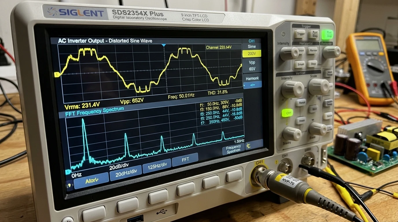
Thermal and Mechanical Impact on Inductive and Non-Linear Loads
Harmonic distortion does not merely represent an aesthetic imperfection on an oscilloscope screen; it exerts severe thermal, acoustic, and mechanical stress on electrical infrastructure.
Parasitic Core Losses and Eddy-Current Overheating in AC Motors
Iron-core magnetic components—including transformers, induction motors, and compressor units—suffer two distinct categories of electromagnetic core loss: hysteresis loss () and eddy-current loss ().
Hysteresis loss scales linearly with operating frequency, while eddy-current loss scales with the square of frequency:
When an induction motor is supplied with distorted inverter voltage containing prominent fifth, seventh, and eleventh harmonics, high-frequency magnetic fluxes induce severe circulating eddy currents within the motor stator laminations:
+------------------------------------------------------------------------------------+
|               INDUCTION MOTOR LOSS MULTIPLIER UNDER INVERTER THD                   |
+------------------------------------------------------------------------------------+
|  WAVEFORM VOLTAGE THD      CORE TEMPERATURE RISE    MOTOR LIFETIME REDUCTION       |
+------------------------------------------------------------------------------------+
|  < 2.0% (Clean Sine Wave)  Baseline (45°C - 55°C)   100% Expected Design Life      |
|  3.0% to 5.0% (Acceptable) +5°C to +8°C Rise        85% Design Life (Minor Stress) |
|  6.0% to 10.0% (High THD)  +15°C to +25°C Rise      50% Design Life (Severe Aging) |
|  > 15.0% (Modified Sine)   +35°C to +50°C Rise      Under 20% Life (Fast Burnout)  |
+------------------------------------------------------------------------------------+
According to the classical Arrhenius thermal insulation rule: every ten-degree Celsius increase in continuous motor winding operating temperature cuts insulation lifespan in half. An off-grid homestead well pump operating on an inverter with eight to ten percent THD runs fifteen to twenty degrees hotter around the clock, accelerating stator insulation breakdown and causing premature motor burnout years before its expected mechanical retirement.
Furthermore, the interaction between forward-rotating and reverse-rotating harmonic magnetic fields creates cyclic mechanical vibration across rotor shafts and end-bearings, generating distinctive acoustic hums and accelerating bearing race pitting.
Power Factor Degradation and Crest Factor Stress on Capacitors
In non-linear electrical environments, traditional Displacement Power Factor () fails to capture the true phase relationship between voltage and current. Instead, engineers must calculate True Power Factor ():
Where the Distortion Power Factor () is directly derived from Current Total Harmonic Distortion:
When harmonic currents increase, distortion power factor plummets. An off-grid inverter may indicate that an appliance draws five hundred watts of real power, yet the internal power stage must circulate seven hundred and fifty volt-amperes of apparent power due to harmonic distortion currents (). This unmetered harmonic current circulates through inverter battery cables and output filter capacitors, causing parasitic heating and triggering premature thermal de-rating of inverter electronics.
Diagnostic Benchmarking: Oscilloscope and Power Quality Telemetry
Accurately diagnosing harmonic distortion in an off-grid installation requires specialized field test instrumentation capable of calculating Fast Fourier Transforms (FFT).
+------------------------------------------------------------------------------------+
|             LABORATORY TELEMETRY: INVERTER HARMONIC BENCHMARK TEST                 |
+------------------------------------------------------------------------------------+
|  INVERTER UNDER TEST: 6,000W Pure Sine Wave Split-Phase Off-Grid Inverter          |
|  LINE VOLTAGE: 241.4V AC RMS | FUNDAMENTAL FREQUENCY: 60.03 Hz                    |
|                                                                                    |
|  LOAD CONDITION: 3,500W Non-Linear Load (Rectifiers, Power Supplies, LED Drivers)  |
|                                                                                    |
|  HARMONIC SPECTRUM TELEMETRY:                                                      |
|  - Fundamental (1st - 60 Hz):     240.2 V RMS  (100.0%)                            |
|  - Third Harmonic (3rd - 180 Hz):  12.4 V RMS   (5.16%)  [Triplen Peak]           |
|  - Fifth Harmonic (5th - 300 Hz):  14.8 V RMS   (6.16%)  [Braking Sequence Peak]  |
|  - Seventh Harmonic (7th - 420 Hz): 7.2 V RMS   (3.00%)                            |
|  - Ninth Harmonic (9th - 540 Hz):   3.1 V RMS   (1.29%)                            |
|  - Eleventh Harmonic (11th - 660):  4.6 V RMS   (1.91%)                            |
|                                                                                    |
|  COMPUTED OVERALL VOLTAGE THD:    7.81% THD_V   [EXCEEDS IEEE 5% LIMIT]            |
|  COMPUTED CURRENT THD:           28.40% THD_I   [SEVERE PEAK CLIPPING]             |
+------------------------------------------------------------------------------------+
Harmonic Spectrum Analysis with Precision Power Analyzers
To measure harmonics in the field, technicians connect a certified Class A power quality analyzer (such as a Fluke 435 Series II, Hioki PW3198, or AEMC 8336) directly across the inverter output terminals:
-
RMS Voltage and Current Waveform Capture: Verify that peak voltage () conforms to pure sine wave proportions. In a clean one hundred and twenty volt RMS system, peak voltage must reach approximately one hundred and seventy volts:
Under heavy harmonic distortion, wave peaks are flattened (flat-topping), reducing the crest factor below one point three, which starves internal DC power supplies in electronic devices.
-
FFT Spectrum Bar Chart Audit: Inspect individual harmonic amplitudes up to the fiftieth harmonic order (, or three thousand hertz). Verify that individual harmonic voltages do not exceed three percent of the fundamental amplitude.
-
Triplen Harmonic Current Audit on Neutral Conductors: In split-phase 120V/240V installations, triplen harmonics () do not cancel out in the neutral conductor; instead, they add up arithmetically. In homes with heavy LED lighting, variable speed heat pumps, and computer servers, neutral conductor currents can exceed the line conductor current even when loads appear balanced across phases.
IEEE Compliance Limits and Generator Paralleling Challenges
IEEE Standard 519 establishes strict power quality benchmarks for electrical power systems:
- General System Voltage Limit: Maximum allowable voltage Total Harmonic Distortion is five percent ().
- Individual Harmonic Voltage Limit: No single harmonic component may exceed three percent () of the fundamental voltage.
When an off-grid solar inverter parallels with an auxiliary backup diesel or propane generator (AC-coupling or hybrid charging), high inverter harmonic distortion creates severe control instability. Distorted voltage waveforms trigger false zero-crossing detections within generator electronic governors and Automatic Voltage Regulators (AVRs), causing generator frequency hunting, surging, and sudden contactor disconnections.
Engineering Solutions: Passive Line Reactors and Active Filtering Architecture
Eliminating harmonic distortion requires targeted electrical engineering interventions at the inverter output stage and distribution panel.
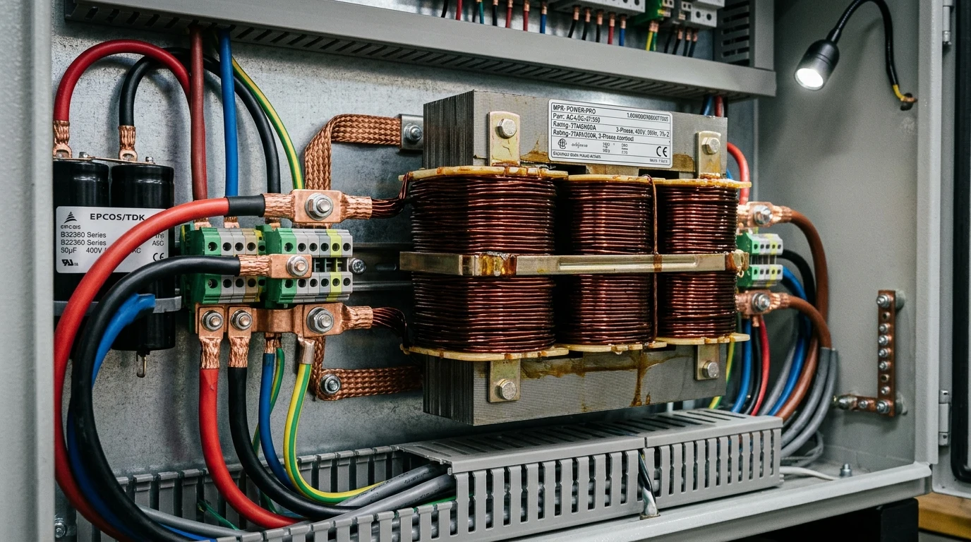
Line Reactors and Tuned Passive Low-Pass Output Filters
The simplest, most cost-effective solution for suppressing harmonic distortion in off-grid power systems is the installation of an AC Line Reactor (inductive choke coil):
+------------------------------------------------------------------------------------+
|               AC LINE REACTOR AND LC HARMONIC FILTER WIRING TOPOLOGY               |
+------------------------------------------------------------------------------------+
|                                                                                    |
|  [ Solar Inverter Output ]                                                         |
|         |                                                                          |
|         v                                                                          |
|  [ Series Line Reactor Choke (L) ] ===> Limits dI/dt, blunts harmonic spikes       |
|         |                                                                          |
|         +-----------------------+                                                  |
|         |                       |                                                  |
|         v                       v                                                  |
|  [ Parallel Shunt Cap (C) ]  [ Protected Subpanel Loads ]                          |
|         |                    - Well Pump / Compressors (Clean Sine Wave)           |
|         v                    - Sensitive Laboratory Electronics                    |
|  [ Grounded Neutral ]                                                              |
|                                                                                    |
+------------------------------------------------------------------------------------+
A line reactor consists of heavy enameled copper magnet wire wound around laminated silicon steel cores, engineered to introduce a precise percentage of inductive reactance into the AC circuit:
- Three-Percent Impedance Line Reactor (): Installed between the inverter output and major subpanels, a three-percent reactor blunts rapid current rise times (), suppresses voltage flat-topping, and reduces current THD from over thirty percent down to under twelve percent.
- Five-Percent Impedance Line Reactor (): Mandatory for severe industrial loads, large variable frequency drives (VFDs), and heavy deep-well submersible pump motors. A five-percent reactor attenuates fifth and seventh harmonic currents by more than sixty percent, completely eliminating motor counter-rotational braking torque.
For specialized off-grid applications requiring laboratory-grade power, engineers deploy Tuned Passive LC Filters. An LC filter combines series inductors with parallel high-voltage polypropylene film capacitors tuned specifically to short-circuit the fifth and seventh harmonic frequencies to neutral, restoring voltage THD below two point five percent.
Active Harmonic Mitigation and Inverter Load De-Rating Protocols
When passive line reactors are insufficient or excessive non-linear loads dominate an off-grid installation, certified engineers execute two critical operational protocols:
- Active Harmonic Filters (AHF): An active harmonic filter is a specialized solid-state device that monitors load current in real time using high-speed current transformers (CTs). When the AHF detects harmonic distortion currents, its internal IGBT bridge synthesizes an exact mirror-image counter-harmonic current ( out of phase), injecting it into the busbar to cancel out the distortion dynamically.
- Inverter Harmonic De-Rating Factor: When operating inverters under heavy non-linear loads with current THD exceeding twenty percent, the inverter continuous power rating must be de-rated according to the harmonic crest factor:
For example, a six-thousand-watt inverter powering an array of non-linear server racks and variable-speed compressors exhibiting twenty-five percent current THD must be de-rated to four thousand five hundred watts continuous capacity to prevent thermal overload of internal power semiconductors.
Complete Solar Inverter Power Quality and Harmonic Commissioning Checklist
To guarantee long-term power purity and protect costly off-grid appliances from harmonic destruction, electrical contractors follow this commissioning protocol:
+------------------------------------------------------------------------------------+
|             COMMISSIONING CHECKLIST: INVERTER POWER QUALITY ASSURANCE              |
+------------------------------------------------------------------------------------+
|  STEP  TEST PHASE          VERIFICATION ACTION                 ACCEPTANCE CRITERIA |
+------------------------------------------------------------------------------------+
|  01    Idle Baseline       Measure no-load inverter output     Voltage THD < 2.5%  |
|                            voltage with Class A power analyzer.Crest Factor: 1.414 |
|                                                                                    |
|  02    Linear Load Audit   Apply 50% resistive load bank       Voltage THD < 3.0%  |
|                            (electric heaters, tungsten lamps). Frequency: 60.0 Hz  |
|                                                                                    |
|  03    Non-Linear Stress   Energize all variable speed heat    Voltage THD < 5.0%  |
|                            pumps, computers, and LED systems.  No single harm > 3% |
|                                                                                    |
|  04    Motor Thermal Scan  Measure well pump casing temp       Winding delta-T     |
|                            after 60 minutes running on inverterunder 20°C above    |
|                            versus pure utility reference.      ambient reference.  |
|                                                                                    |
|  05    Neutral Conductor   Audit triplen harmonic current on   Neutral current must|
|                            shared split-phase neutral busbar   not exceed line     |
|                            under maximum unbalanced loads.     conductor rating.   |
|                                                                                    |
|  06    Line Reactor InstallInstall 3% to 5% impedance choke    Restores voltage THD|
|                            ahead of inductive motor circuits   under 5.0% under all|
|                            if 5th harmonic exceeds 4.0%.       operating states.   |
+------------------------------------------------------------------------------------+
By systematically auditing inverter harmonic spectra, sizing low-frequency toroidal hardware for surge-heavy homesteads, and integrating inductive line reactors across non-linear circuits, solar engineers eliminate electrical noise at the source, ensuring seamless off-grid power quality and decades of reliable appliance operation.