In off-grid homesteads, modern cabins, and emergency backup installations, North American residential electrical infrastructure requires split-phase power. While lighting, kitchen small appliances, and entertainment electronics operate on standard one hundred and twenty volts alternating current (120V AC), heavy residential inductive loads—such as deep-well submersible water pumps, central heat pump compressors, electric clothes dryers, and electric vehicle chargers—demand two hundred and forty volts alternating current (240V AC).
Many entry-level and mid-tier solar inverters (such as Victron MultiPlus, Schneider Conext, Outback FX, and EG4 units), as well as portable power stations (EcoFlow Delta Pro, Bluetti, Jackery), are fundamentally single-phase 120V machines.
To power a standard household distribution panel, installers execute an engineering technique known as Inverter Stacking: interconnecting two identical 120V inverters so that their alternating current output waveforms operate locked in opposite phase, delivering two individual 120V hot legs (Line One and Line Two) that combine to provide 240V phase-to-phase potential.
However, stacking inverters is far more complex than simply twisting wires together. Without microsecond phase synchronization, active vector load balancing, and common-trip overcurrent protection, stacked systems can trigger explosive short-circuits, back-feed dead inverters, and overload neutral conductors.
This engineering guide examines the mathematics of split-phase synchronization, diagrams high-speed master-slave Phase-Lock Loop (PLL) communication, calculates vector neutral current flows, and details code-compliant physical wiring architectures.

Executive Summary: The Engineering Challenge of Stacking Independent Inverters
In a standard utility split-phase service, alternating current is supplied by a center-tapped utility distribution transformer. The magnetic flux within the transformer’s single iron core physically guarantees that the two outer hot legs are permanently and immutably synchronized exactly one hundred and eighty degrees apart ( phase displacement):
The potential difference measured across the two outer conductors is the instantaneous difference between the two out-of-phase waveforms:
When dealing with two separate, solid-state solar inverters, however, there is no shared physical transformer core. Each inverter contains its own autonomous crystal oscillator clock, micro-controller, and high-frequency switching bridge:
+------------------------------------------------------------------------------------+
|               THE CATASTROPHIC DANGER OF UN-SYNCHRONIZED INVERTERS                 |
+------------------------------------------------------------------------------------+
|                                                                                    |
|  SCENARIO A: IDENTICAL PHASE (0° Offset):                                          |
|  - Inverter 1: 120V AC RMS                                                         |
|  - Inverter 2: 120V AC RMS (In-Phase)                                             |
|  - Line-to-Line Voltage: 120V - 120V = 0 Volts! (Cannot power 240V appliances!)    |
|                                                                                    |
|  SCENARIO B: DRIFTING RANDOM PHASE (e.g. 90° Offset):                              |
|  - Line-to-Line Voltage fluctuates randomly between 0V and 240V.                   |
|  - Motor magnetic fields fluctuate violently, causing extreme inductive burnout.   |
|                                                                                    |
|  SCENARIO C: TRUE LOCKED SPLIT-PHASE (Exactly 180.0° Offset):                      |
|  - Inverter 1 (Line 1): 120V AC RMS                                                |
|  - Inverter 2 (Line 2): 120V AC RMS (180° Inverted)                                |
|  - Line-to-Line Voltage: 120V - (-120V) = 240 Volts RMS (Stable Utility Standard)  |
|                                                                                    |
+------------------------------------------------------------------------------------+
If two inverters attempt to power a shared electrical panel without active digital synchronization, phase drift will cause the line-to-line voltage to modulate erratically. When connecting a 240V well pump motor across drifting phases, the fluctuating rotational magnetic field induces destructive counter-torques that stall the motor and trip inverter overcurrent protection within cycles.
Mathematical Physics of Split-Phase Alternating Current Synchronization
Achieving a stable 240V split-phase distribution system requires strict mathematical phase locking between the two inverter power stages.
Symmetrical Phase Angle Displacement and Phase-to-Phase Voltage Math
In an alternating current circuit, root-mean-square (RMS) voltage measured between two conductors () having arbitrary phase displacement angle () is expressed by the law of cosines in vector form:
When both inverters produce an identical nominal voltage ():
-
If inverters operate in parallel ( phase shift, ):
This configuration is used for Parallel Stacking (combining two inverters onto a single 120V busbar to double current capacity to eighty amperes).
-
If inverters operate in split-phase ( phase shift, ):
        Line 1 Vector (120V @ 0°) ---------> (Origin) <--------- Line 2 Vector (120V @ 180°)
        <======================= Total Vector Distance: 240V =======================>
Vector Summation and Shared Neutral Current Dynamics
In a residential split-phase electrical subpanel, 120V branch circuits (lighting, outlets) return current along a single shared neutral conductor.
The instantaneous current flowing through the neutral wire () is the Kirchhoff sum of the return currents from Line One () and Line Two ():
Because Line One and Line Two operate one hundred and eighty degrees out of phase, their current waveforms possess opposing signs:
+------------------------------------------------------------------------------------+
|               SHARED NEUTRAL CURRENT VECTOR CANCELLATION DYNAMICS                  |
+------------------------------------------------------------------------------------+
|  LOAD CONDITION         LINE 1 CURRENT    LINE 2 CURRENT    SHARED NEUTRAL CURRENT |
+------------------------------------------------------------------------------------+
|  Perfectly Balanced     20.0 Amperes      20.0 Amperes      0.0 Amperes (Zero Net!)|
|  Moderate Imbalance     25.0 Amperes      15.0 Amperes      10.0 Amperes (Vector Δ)|
|  Total Imbalance        30.0 Amperes      0.0 Amperes       30.0 Amperes (Full L1) |
|  Pure 240V Load         18.0 Amperes      18.0 Amperes      0.0 Amperes (No Neutral|
+------------------------------------------------------------------------------------+
When loads are perfectly balanced (twenty amperes on Line One and twenty amperes on Line Two), the currents cancel out completely, and the neutral conductor carries zero amperes of return current.
However, if an installer turns off all loads on Line Two while running a thirty-ampere workshop tool on Line One, the neutral conductor must carry the full uncancelled thirty amperes. Therefore, the shared neutral conductor must never be downsized; it must be sized to carry the maximum rated continuous output of the largest individual stacked inverter.
Asymmetric Load Imbalance and Inverter Back-Feeding Hazards
A primary failure mode in stacked inverter systems occurs during severe asymmetric loading.
When a massive 120V single-phase inductive load (such as a large air compressor or table saw) starts on Line One, the instantaneous inrush current can cause internal voltage sag on Inverter One. If Inverter One sags to one hundred and ten volts while Inverter Two remains at one hundred and twenty-three volts, the voltage difference across a connected 240V appliance creates internal circulating currents.
Even more dangerously, if Inverter One trips offline on thermal overload while Inverter Two continues running, a multi-phase appliance (such as an electric oven or water heater element) can conduct current from Inverter Two through its internal resistive elements directly into the output terminals of the dead Inverter One. This reverse back-feeding can destroy the output filtering MOSFETs of the deactivated inverter unless common-trip protection is installed.
Master-Slave Digital Communication and Phase-Lock Loop Architecture
To maintain absolute phase coherence, stacked inverters rely on continuous, deterministic digital communication.
High-Speed Optical and Serial Bus Synchronization Protocols
Stacked inverters are configured in a Master-Slave Hierarchy:
- Master Inverter (Phase Leader): Internal microprocessor crystal clock establishes the baseline sixty-hertz sinusoidal reference waveform ().
- Slave Inverter (Phase Follower): Deactivates its autonomous internal clock. Instead, its internal Phase-Lock Loop (PLL) locks its PWM switching timing directly to the high-speed synchronization pulses transmitted by the Master.
+------------------------------------------------------------------------------------+
|               MASTER-SLAVE PHASE-LOCK LOOP SYNCHRONIZATION BUS                     |
+------------------------------------------------------------------------------------+
|                                                                                    |
|  [ MASTER INVERTER (L1) ]                                                          |
|  - Autonomous Quartz Clock (60.000 Hz)                                             |
|  - Phase Reference: 0.00°                                                          |
|         |                                                                          |
|         | === High-Speed Digital Sync Bus (CAN-bus / RS-485 / Optical Fiber) ===>   |
|         | (Transmits Zero-Crossing Pulse every 8.33 milliseconds)                  |
|         v                                                                          |
|  [ SLAVE INVERTER (L2) ]                                                           |
|  - Internal Clock Slave-Locked                                                     |
|  - Phase-Lock Loop (PLL) applies exact 180.00° phase displacement                  |
|  - Symmetrical Voltage Tracking Loop                                               |
|                                                                                    |
+------------------------------------------------------------------------------------+
Communication is carried over shielded twisted-pair cables (typically CAT5e or CAT6 with RJ45 terminations, or dedicated high-speed optical fiber links). Every eight point three three milliseconds (at every alternating current zero-crossing point), the Master sends a digital hardware interrupt pulse to the Slave.
The Slave’s internal DSP adjusts its PWM pulse train dynamically, maintaining phase alignment within a tight tolerance of less than zero point one electrical degrees:
Firmware Revisions and Microcontroller Timing Jitter Vulnerabilities
In stacked inverter systems, firmware uniformity is absolute law.
If an installer stacks two inverters where Inverter One runs firmware version two point four and Inverter Two runs version two point six, minute differences in the compiled code execution cycles can introduce microsecond timing delays in the interrupt service routines.
A timing jitter of just eighty microseconds () at sixty hertz represents nearly two electrical degrees of phase error:
This phase error creates continuous circulating reactive currents between the two inverters, causing high idle standby power draw, buzzing output chokes, and nuisance communication-loss fault trips (often displayed as Error Code 08 or Error Code 60 on hybrid inverters).
Physical Wiring Topologies: Distribution Panels and Transfer Switches
Safely translating stacked inverter outputs into household power requires strict adherence to National Electrical Code (NEC) wiring architectures.

Multi-Pole Overcurrent Breakers and Common-Trip Interlocks
The most crucial overcurrent protection requirement for stacked inverters is the installation of a Common-Trip Multi-Pole Circuit Breaker.
+------------------------------------------------------------------------------------+
|               COMMON-TRIP OVERCURRENT PROTECTION TOPOLOGY                          |
+------------------------------------------------------------------------------------+
|                                                                                    |
|  [ Master Inverter (L1) ] ======> [ Breaker Pole 1 ] --+                           |
|                                                        | === Mechanical Tie Bar    |
|  [ Slave Inverter (L2) ]  ======> [ Breaker Pole 2 ] --+     (Common-Trip Interlock)|
|                                                        |                           |
|  [ Shared Neutral (N) ]   ======> [ Solid Neutral Bus ]|                           |
|                                                        |                           |
|  RESULT: If Inverter 1 trips on overload, the internal handle tie mechanically    |
|  disconnects Inverter 2 at the exact same instant, preventing backfeed damage.     |
+------------------------------------------------------------------------------------+
Installers must never use two independent, unlinked single-pole breakers to connect stacked inverters to a distribution panel. Under NEC Article 240.15(B), multi-wire branch circuits and multi-phase supply sources must utilize a two-pole common-trip breaker equipped with an internal trip bar.
If Inverter One experiences a sudden short-circuit or thermal trip, the breaker handle tie guarantees that both Line One and Line Two are severed simultaneously, instantly isolating all 240V loads and preventing dangerous back-feeding.
Neutral-Ground Bonding Rules Across Stacked Chassis Enclosures
Neutral-to-ground bonding in stacked inverter systems is governed by the universal electrical mandate: exactly one neutral-to-ground bond per separately derived system.
Many modern 120V hybrid inverters feature internal dynamic bonding relays that automatically connect the neutral output terminal to the metal chassis when operating in off-grid battery mode.
In a stacked configuration:
- The Double-Bond Trap: If both Inverter One and Inverter Two leave their internal bonding relays enabled, two separate neutral-ground bonds exist simultaneously. Return neutral current will split between the neutral wire and the equipment grounding conductors, causing hazardous objectionable currents on metal conduit and tripping upstream GFCIs.
- Code-Compliant Solution: Disable the internal bonding relays on both inverters (via firmware settings or physical internal jumper removal). Route the Line One, Line Two, Neutral, and Equipment Ground conductors to the primary AC subpanel. Establish a single, solid neutral-to-ground bonding strap inside the subpanel enclosure, bonded directly to the grounding electrode system (ground rods).
Complete Inverter Stacking Commissioning and Phase Synchronization Checklist
Before closing the main AC breakers on a newly stacked inverter system, certified technicians execute this rigorous commissioning protocol:
+------------------------------------------------------------------------------------+
|             ENGINEERING COMMISSIONING CHECKLIST: INVERTER STACKING                 |
+------------------------------------------------------------------------------------+
|  STEP  PHASE               ACTION ITEM                         SPECIFICATION       |
+------------------------------------------------------------------------------------+
|  01    Firmware Audit      Verify Identical Firmware Revisions Exact Match Required|
|                            Flash both inverters to the exact   Zero version delta  |
|                            same firmware release build prior   allowed across micro|
|                            to connecting communication cables. controller chips.   |
|                                                                                    |
|  02    Hardware Hierarchy  Configure Master-Slave Roles        DIP Switches / App  |
|                            Set Unit 1 to "Master / Phase L1";  Confirm Master LED  |
|                            set Unit 2 to "Slave / Phase L2";   solid; Slave LED    |
|                            install terminator resistors on bus.indicates sync lock.|
|                                                                                    |
|  03    Bonding Audit       Disable Internal Bonding Jumpers    Check with Ohmmeter |
|                            Ensure neither inverter bonds       Continuity between  |
|                            neutral to chassis internally; bond neutral and chassis |
|                            only at central AC distribution box.must read infinite. |
|                                                                                    |
|  04    Phase Verification  Execute No-Load Multimeter Audit    Digital Multimeter  |
|                            Measure L1 to Neutral: 120V ± 2V    L1 to L2 MUST read  |
|                            Measure L2 to Neutral: 120V ± 2V    238V to 242V AC RMS |
|                            Measure L1 to L2: 240V ± 4V.        prior to closing load|
|                                                                                    |
|  05    Oscilloscope Scan   Confirm 180° Phase Angle Lock       Dual-Channel Scope  |
|                            Verify zero-crossing synchronizationChannel 1 vs Chan 2 |
|                            with high-voltage probes; confirm   must show smooth    |
|                            zero phase jitter under idle state. opposite sine waves.|
|                                                                                    |
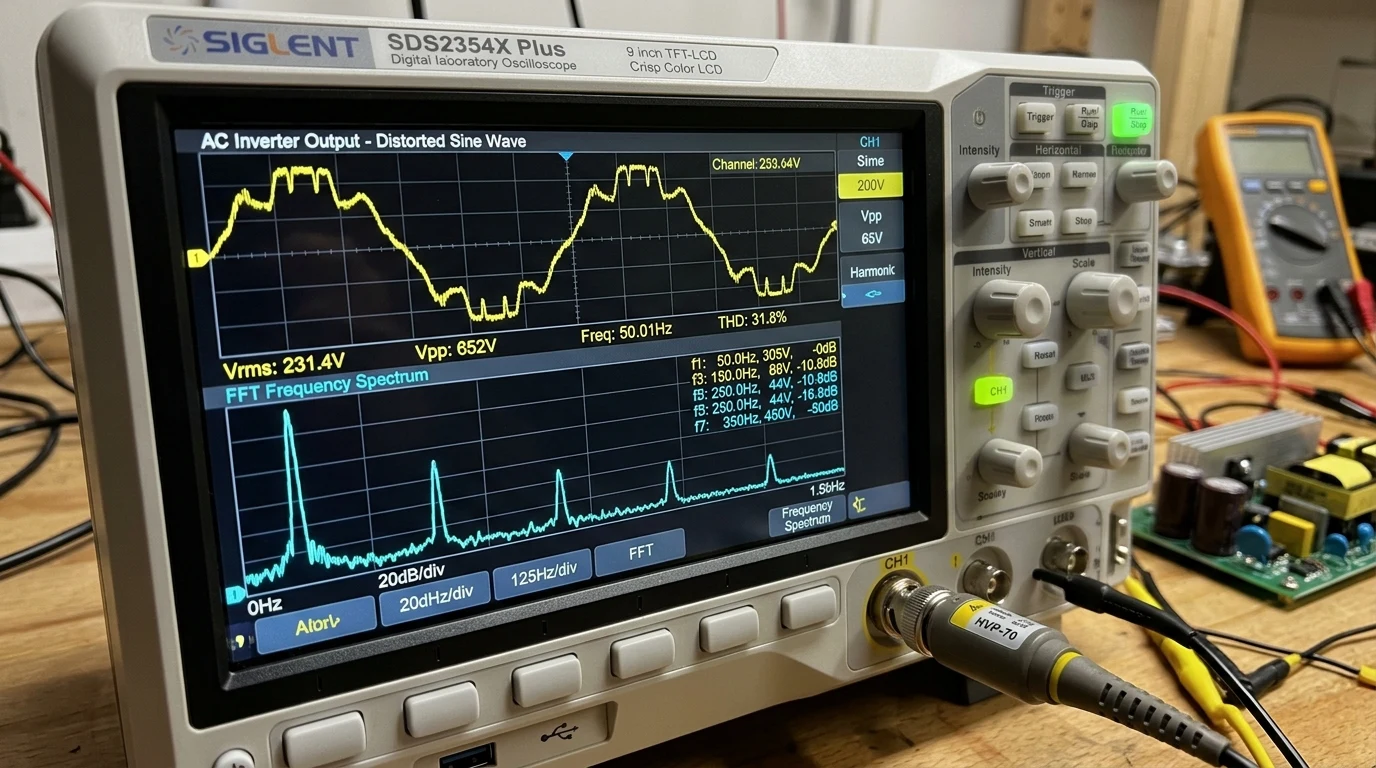
|  06    Asymmetric Load TestAudit Shared Neutral Current        Clamp Ammeter Test  |
|                            Apply 20A load on L1 and 0A on L2;  Neutral current must|
|                            verify neutral carries exactly 20A; equal difference; zero|
|                            apply balanced 240V load, verify 0A.overheating on wire.|
+------------------------------------------------------------------------------------+
By engineering inverter stacking as an integrated, synchronized power generation system—mandating identical firmware, verifying one-hundred-and-eighty-degree phase locking on dual-channel oscilloscopes, and establishing common-trip breaker protection—off-grid homesteaders and solar engineers unlock reliable, heavy-duty 240V split-phase power capable of running demanding well pumps, workshop machinery, and household appliances with utility-grade stability.