Executive Summary: The Non-Export Dilemma in Modern Hybrid Solar Systems
Across residential and light-commercial electrical grids, utility interconnection policies have grown increasingly restrictive. While early solar adopters enjoyed generous one-to-one retail net metering, modern grid operators have introduced complex regulatory hurdles:
- Net Energy Metering Surcharges (NEM Three Point Zero): Wholesale avoided-cost export compensation rates have slashed the financial value of grid-injected solar energy by seventy to eighty-five percent.
- Non-Export Interconnection Agreements: Many suburban and rural municipal utilities, electric cooperatives, and distribution utilities enforce strict zero-export tariffs. Homeowners are permitted to install rooftop solar exclusively for on-site self-consumption, with contractual prohibitions against back-feeding even a single watt-hour into the distribution network.
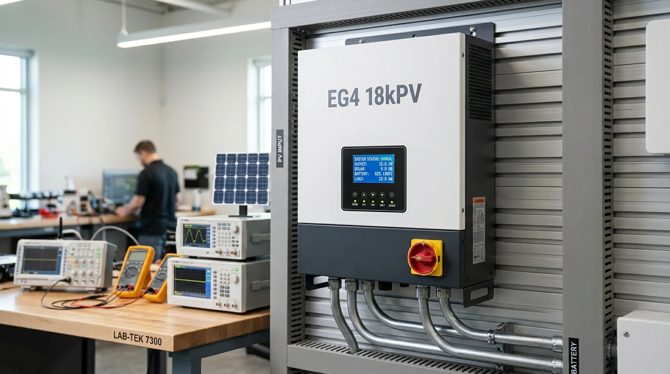
- Permission to Operate (PTO) Waiting Windows: Installing high-capacity hybrid inverters (such as an EG4 eighteen-kPV, Sol-Ark fifteen-k, Schneider Conext, or Deye twelve-kilowatt unit) often requires months of permitting delays before formal grid export approval is granted.
To harvest free solar power immediately while avoiding unauthorized export fines, system designers rely on Zero-Export (Anti-Backflow / Limit-to-Home) operational profiles.
In a zero-export architecture, the hybrid inverter dynamically throttles its photovoltaic DC-to-DC converters and battery inverter stages in real time, matching total AC output precisely to the household electrical consumption. However, achieving flawless zero-export control requires high-precision current sensing. Minor installation errors—such as reversed Current Transformer (CT) polarity, cross-phased voltage references, or electromagnetic noise on instrumentation wiring—trigger catastrophic control failures that back-feed the grid or trip utility anti-fraud smart meters.
Operating Principles of Closed-Loop Zero-Export Architectures
Real-Time Power Flow Sensing and Dynamic Curtailment Logic
At its fundamental control level, zero-export operation is a closed-loop negative feedback system governed by high-speed Digital Signal Processors (DSP).
The hybrid inverter must continuously solve the nodal power balance equation at the main electrical service entrance:
Where:
- is the net active power exchanged with the utility distribution grid (positive for import; negative for export).
- is the instantaneous power consumed by all household appliances, lighting, and HVAC machinery.
- is the total power harvested by the rooftop photovoltaic array through Maximum Power Point Tracking (MPPT) stages.
- is the power discharged from (positive) or absorbed by (negative) the lithium storage bank.
In pure zero-export mode, the inverter’s control objective is to maintain at all times. When rooftop solar generation exceeds household consumption, the DSP controller takes one of two automated actions:
- Battery Diversion: Surplus solar current is redirected through the internal bi-directional DC-DC battery charger to recharge depleted battery cells.
- MPPT Power Curtailment: If the battery bank is fully charged or restricted by charge-rate parameters, the MPPT controller shifts the PV operating voltage () away from the maximum power point toward the open-circuit voltage (), electronically shedding generation to match household demand down to the exact watt.
Distinguishing Whole-Home Backup from Limited-to-Home Self-Consumption
A critical engineering distinction lies in the physical topology of the electrical distribution panel:
- Whole-Home Backup via Dedicated Load Terminals: In a standard off-grid or critical-loads backup configuration, all sub-panel circuits are connected directly downstream of the inverter’s internal Automatic Transfer Switch (ATS) on the
LOADorUPSterminals. In this layout, internal Hall-effect current sensors track household consumption directly without external metering. - Service Entrance Split-Grid Metering (Partial-Home Backup): In high-amperage residences (two-hundred or four-hundred-ampere services), large inductive loads (such as six-ton central air conditioners, electric vehicle fast chargers, and geothermal heat pumps) remain located in the primary main distribution panel upstream of the inverter. Here, the inverter sits on an AC back-feed breaker. To prevent back-feeding the utility while supplying energy to these heavy upstream loads, the inverter relies entirely on external split-core Current Transformers installed at the main utility service drop.
Grid Interconnection Agreement Rules and Anti-Backflow Penalties
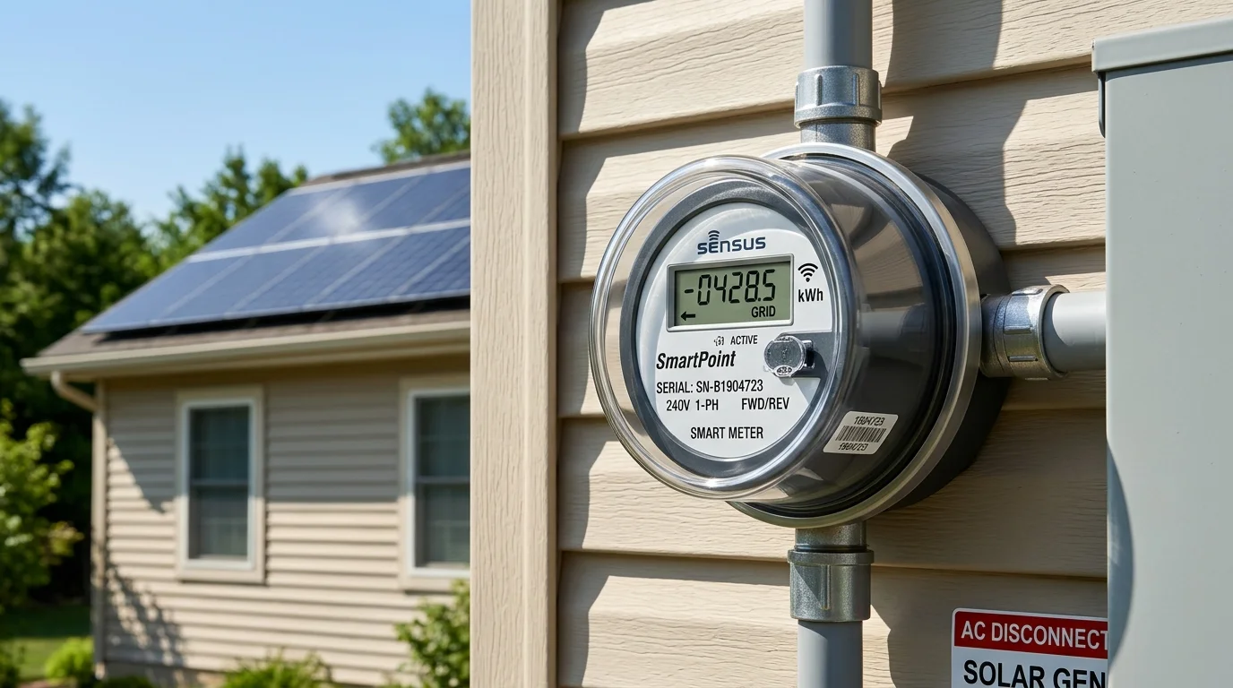
Utility companies enforce non-export agreements through automated software audits embedded in solid-state bidirectional smart meters.
Under non-export rules:
- Any persistent reverse current flow is flagged by the utility’s automated meter reading network.
- Some legacy digital meters lack bidirectional net calculation registers and simply sum all current vectors as positive consumption, meaning the utility will actually charge you your full retail electricity rate for the power you gave them for free!
- Advanced AMI meters log a “Reverse Energy Fraud Event,” which can prompt automatic disconnect notices or forced transition to punitive utility demand rate structures.
Current Transformer Physics and Service Entrance Metering
Core Saturation and Secondary Current Proportionality
To meter hundreds of amperes of alternating current safely without breaking primary conductors, installers mount split-core Current Transformers over the incoming Line One () and Line Two () service feeders.
A Current Transformer operates on the principle of electromagnetic induction:
- The thick primary service feeder acts as a single-turn primary winding carrying heavy current ().
- The primary alternating current generates an oscillating magnetic flux () inside the laminated silicon steel or ferrite toroidal core.
- The magnetic flux induces a scaled secondary current () in the multi-turn secondary winding (), governed by the turns ratio:
In modern hybrid solar equipment, standard residential CTs are engineered with either:
- Current-Output Architecture: A standard two-thousand-to-one or three-thousand-to-one turns ratio delivering zero to five amperes or zero to thirty-three milliamperes AC secondary output.
- Voltage-Output Architecture: An internal precision burden resistor () pre-installed inside the plastic CT casing, converting the induced secondary current into a safe low-voltage signal:
Standard residential voltage-output CTs output zero to three hundred and thirty-three millivolts AC () at full rated primary current.
Critical Arrow Orientation: Distinguishing Grid Versus Load Directionality
Every split-core current transformer features a directional arrow embossed onto its plastic housing, along with color-coded secondary leads (typically White for positive/signal; Black for negative/ground).
The arrow indicates the polarity of instantaneous active power flow:
- In the vast majority of hybrid solar systems (including Sol-Ark, EG4, Deye, and Luxpower), the physical rule is strict: The arrow must point toward the Home Electrical Load (away from the utility pole or meter base, and toward the main breaker).
- When power flows from the utility into the house, current travels in the direction of the arrow. The secondary waveform generated by the CT is exactly in phase with the line voltage waveform (). The inverter computes positive active power (), correctly recognizing that the home is importing power from the grid.
[!WARNING] If a current transformer is clamped backward with the arrow pointing toward the utility grid, the secondary waveform is inverted by one hundred and eighty degrees (). The inverter interprets normal household appliance consumption as unauthorized solar export!
In response, the inverter’s control loop initiates a runaway positive feedback cycle: believing that power is back-feeding the grid, it aggressively increases solar generation to compensate, causing severe and continuous back-feeding that instantly trips smart meter alarms!
Phase Pairing Discipline: Preventing Phase Cross-Connection Errors
In a North American split-phase electrical service (), Line One and Line Two are separated by one hundred and eighty electrical degrees:
Active power is computed as the product of instantaneous voltage and current integrated over the cycle:
If the installer accidentally swaps the CT sensor wiring—placing Sensor One on the Line Two feeder while connecting it to the Line One terminal block:
- The DSP processor multiplies the Line Two current vector by the Line One voltage reference.
- The calculated phase angle shifts by one hundred and eighty degrees.
- The inverter displays negative wattage on one phase and erratic reactive power on the other, crippling the zero-export throttling algorithm.
Both the physical line clamp and the electronic terminal connection must correspond strictly to the same phase leg.
Dynamic Response Time and Transient Grid Spillage
Inverter Sampling Loop Latency and Digital Signal Processing Delay
A common misconception among homeowners is that a zero-export system never allows a single electron to spill backward into the grid. In reality, zero-export is an electro-mechanical control process with measurable physical latency.
Total system reaction latency () is the sum of several sequential stages:
- Analog Filtering and Analog-to-Digital Conversion: Anti-aliasing passive filters and high-speed ADC converters digitize the CT secondary waveform ().
- DSP True-RMS and Phase Transform Calculation: The processor executes a Fast Fourier Transform (FFT) or synchronous reference frame (-transform) across at least one full sixty-hertz AC cycle to calculate true active power ().
- Proportional-Integral-Derivative (PID) Control Loop Execution: The control algorithm computes the required power step-down ().
- DC-DC Converter Duty Cycle Modulation: Gate drivers adjust the Pulse Width Modulation (PWM) switching frequency to shift the solar array operating voltage ().
- Inductor and Filter Capacitor Discharge: Energy stored within the inverter’s massive DC link capacitors and output inductors must physically dissipate into the grid ().
Consequently, the total closed-loop response time ranges between fifty and two hundred milliseconds ().
Sudden Heavy Load Disconnects and Transient Export Physics
Consider a high-power household scenario:
- A five-kilowatt electric water heater and a four-kilowatt clothes dryer are operating simultaneously, consuming nine thousand watts of power.
- The hybrid inverter is operating in zero-export mode, delivering exactly nine thousand watts of solar power to meet this load. The grid meter registers zero watts.
- Suddenly, the water heater thermostat clicks open, instantly dropping total household consumption from nine thousand watts to four thousand watts in less than two milliseconds.
Because the inverter’s power curtailment loop requires one hundred milliseconds to detect the load drop and throttle its power stage, five thousand watts of surplus solar power is momentarily pushed backward into the utility grid for approximately six to twelve electrical cycles!
The physical energy spilled during this transient event is small:
While negligible in terms of bulk energy, this momentary pulse can be recorded by sensitive smart meters.
Smart Meter Anti-Fraud Accumulators and Bidirectional Sensitivity
Modern digital utility meters contain anti-tamper firmware registers:
- Ferraris Disk Emulation Meters: Integrate active power continuously with directional mechanical inertia, naturally ignoring brief sub-second transient spikes.
- Microprocessor Vector Meters: Some advanced utility smart meters sample voltage and current at thousands of hertz, instantly incrementing an internal “Reverse Energy” register upon detecting any reverse energy packet, regardless of duration.
To ensure absolute zero-export compliance and eliminate transient reverse trips, professional solar engineers implement a Grid Import Power Buffer:
+-----------------------------------------------------------------------------+
|               ZERO-EXPORT POWER BUFFER CONFIGURATION                        |
+-----------------------------------------------------------------------------+
|                                                                             |
|   Target Setpoint: Zero Watts (0W) ---> High Risk of Transient Export Spillage
|   Target Setpoint: Positive 30W Bias -> SAFE: Absorbs 99% of Step Transients |
|                                                                             |
|   [Grid Supply] ----> [30W Constant Trickle] ----> [Main Electrical Panel]  |
|                                                          ^                  |
|                                                          |                  |
|   [Solar Inverter] -> [Supplies 99.5% of Demand] --------+                  |
|                                                                             |
+-----------------------------------------------------------------------------+
By programming the inverter’s zero-export power target to maintain a continuous baseline import of twenty to fifty watts () from the grid:
- When a large appliance shuts down, the transient surplus cuts into the fifty-watt baseline buffer before crossing into actual reverse flow.
- The smart meter never detects net export, eliminating compliance violations while still offsetting over ninety-nine percent of household electricity costs.
Electromagnetic Interference and Instrumentation Cabling Standards
Shielded Twisted-Pair Wiring Rules and Ground Loop Elimination
Current transformer secondary signals are extraordinarily sensitive micro-current or micro-voltage circuits. In a zero-export system, these delicate signals must travel from the main outdoor electrical service entrance to the hybrid inverter, often crossing twenty to one hundred feet through residential basements or exterior walls.
Because solar inverters utilize high-frequency Insulated Gate Bipolar Transistors (IGBTs) switching at sixteen to twenty kilohertz, the surrounding environment is saturated with intense electromagnetic interference (EMI).
To protect CT signal integrity:
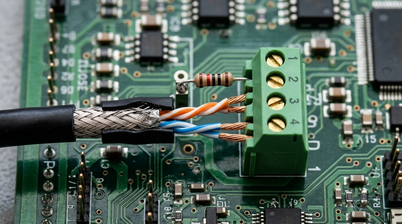
- Twisted-Pair Geometry: Installers must use twisted-pair cabling (such as Belden 8761 or quality CAT6 shielded cable). The continuous twisting ensures that any radiated noise induces identical common-mode voltages in both conductors, which is effortlessly rejected by the inverter’s differential input amplifier.
- Aluminum Foil Shielding: The cable must feature an overall foil shield with an uninsulated tinned copper drain wire to block high-frequency capacitive noise.
- Single-Ended Ground Bonding: The drain shield wire must be grounded at one end only—specifically at the inverter’s chassis ground terminal. Never ground the shield at both the service entrance panel and the inverter! Grounding both ends creates a closed ground loop that carries circulating 60Hz ground current, inducing massive artificial voltage offsets into the CT measurement.
Maximum Extension Distances and Secondary Voltage Drop
Extending CT leads beyond their factory length introduces series wire resistance ().
For Current-Output CTs (5A secondary):
- High secondary current flowing through extended thin wire generates significant resistive voltage drop ().
- If total lead resistance exceeds the CT’s maximum rated burden capacity (volt-ampere rating), the magnetic core saturates, severely distorting current readings. Standard 5A CTs should never be extended more than fifteen to twenty feet using thin wire; sixteen or fourteen-gauge copper is mandatory for longer runs.
For Voltage-Output CTs (333mV secondary):
- The burden resistor is internal, and the secondary current is tiny (microamperes).
- While burden saturation is eliminated, extended wire runs face signal attenuation and capacitive noise pickup. Voltage-output CTs can be safely extended up to one hundred feet (), provided eighteen-gauge shielded twisted-pair wire is utilized.
Engineering Benchmark Matrix: Zero-Export Control Methods and Hardware Specifications
The following comparative matrix details the technical trade-offs across common zero-export sensing architectures:
| Parameter | Split-Core Voltage CT (333mV) | Split-Core Current CT (5A) | Modbus RS485 Smart Energy Meter |
|---|---|---|---|
| Typical Secondary Signal | Digital Data Packets () | ||
| Measurement Response Latency | Ultra-Fast ( analog) | Ultra-Fast ( analog) | Moderate ( polling cycle) |
| Maximum Safe Extension Run | Up to with STP | Up to (requires heavy wire) | Up to via RS485 differential bus |
| Open-Circuit Hazard | Zero danger (burden is internal) | High voltage arcing hazard if open | Zero danger (galvanically isolated) |
| Installation Complexity | Simple clip-on around service wires | Simple clip-on (mind burden rating) | Requires inline DIN-rail meter mounting |
| Noise Immunity | Sensitive to EMI; demands shielding | Excellent current-loop noise immunity | Perfect (digital checksums and CRC verification) |
| Transient Spillage Risk | Minimal ( total loop) | Minimal ( total loop) | Higher ( polling latency) |
| Common Hardware Examples | Sol-Ark 15K / EG4 18kPV standard | Commercial Solar Gateways / Accuenergy | Victron EM24 / Carlo Gavazzi / Chint DDSU |
Field Diagnostic and Commissioning Checklist for Zero-Export Systems
Validating Power Directionality in Inverter Firmware Dashboards
Prior to energizing rooftop solar arrays in zero-export mode, execute this mandatory commissioning verification:
- Keep Solar Array Disconnected: Open all PV DC isolator switches or breakers so solar generation is strictly zero watts.
- Verify Battery Idling: Set the battery to idle so no energy discharges to AC loads.
- Turn On a Known Resistive Load: Switch on an electric space heater, toaster, or clothes dryer (e.g., a two-kilowatt load) downstream of the electrical panel.
- Audit Firmware Telemetry:
- Observe the inverter’s main touchscreen or web monitoring dashboard.
- Grid power must display positive consumption (+2.0kW import).
- Power factor should read close to unity ().
- Both Line One and Line Two must display positive wattage.
- Failure Sign: If the grid reading displays negative wattage (), or if power factor reads negative, the CT arrow on that phase is installed backward. De-energize and flip the CT physical orientation immediately.
Step-by-Step Load Testing to Confirm Perfect Anti-Backflow Suppression
Once sensor directionality is verified:
- Activate PV Solar Generation: Close the DC string isolators and allow the MPPT controllers to acquire maximum power.
- Observe Zero-Export Throttling: Confirm that the inverter ramps AC generation to match household consumption while grid power stabilizes at your programmed buffer (e.g., ).
- Execute Abrupt Step-Load Shedding: While the solar array is producing four to six kilowatts, suddenly trip the main appliance load breaker.
- Monitor Grid Meter Telemetry: Watch the utility smart meter’s digital display. Ensure that no reverse energy warning annunciator illuminates and that the kilowatt-hour pulse indicator does not register reverse increments.
By adhering to rigorous current transformer orientation rules, enforcing strict phase pairing, utilizing shielded instrumentation cabling, and programming an adequate positive grid buffer, system installers can deploy high-power hybrid solar systems that operate with complete regulatory safety and zero grid spillage.