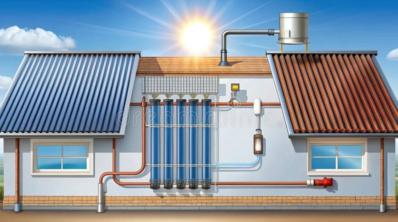
In regions that experience severe winter freezes, designing a solar water heating system has historically meant accepting a messy chemical compromise: filling rooftop solar thermal collectors with a mixture of water and inhibited propylene glycol.
While pressurized closed-loop glycol systems prevent freezing down to sub-zero temperatures, they introduce a host of severe long-term maintenance headaches: glycol degrades under high summer stagnation temperatures, turns acidic (dropping below pH 7.0), strips protective copper oxide layers, corrodes pump impellers, and requires annual hydronic fluid testing and costly fluid replacement every three to five years.
A solar drainback system completely eliminates the need for anti-freeze chemicals.
Instead of fighting gravity and sub-zero temperatures with chemical additives, a drainback system utilizes fundamental gravity physics: it circulates plain, distilled water through rooftop collectors only when useful solar energy is available. The exact microsecond the circulation pump shuts off—whether due to sunset, passing heavy clouds, a satisfied hot water thermostat, or a utility power outage—every drop of water on the roof immediately drains back into an insulated indoor reservoir tank located safely within the conditioned building envelope.
In this engineering guide, the GridSpecLab hydronics team details the physics of drainback thermal loops, outlines the non-negotiable piping slope rules required to prevent freeze-ups, provides mathematical equations for pump head sizing, and explores controller commissioning for maximum reliability.
A solar drainback system is the most mechanically elegant, low-maintenance solar thermal architecture ever devised. By relying on gravity rather than chemical glycol, it eliminates fluid degradation, heat exchanger fouling, and stagnation steam blow-offs. However, drainback success demands flawless mechanical execution: a strict minimum 1/4-inch per foot continuous downward slope on all horizontal pipe runs, a high-head circulation pump sized to overcome total static vertical lift, and an adequately sized indoor drainback reservoir.
Compare Solar Thermal vs PV Heat Pumps →
Core Operating Principle: Gravity-Powered Fail-Safe Freeze Protection
The architecture of a drainback system is deceptively simple: it consists of rooftop collectors, an indoor drainback reservoir tank (which often incorporates an internal heat exchanger coil), a high-head circulation pump, a domestic storage water heater, and a differential temperature controller.
+-----------------------------------------------------------------------------------------+
|                  SOLAR DRAINBACK HYDRONIC SYSTEM SCHEMATIC TOPOLOGY                     |
+-----------------------------------------------------------------------------------------+
|                                                                                         |
|       [Rooftop Solar Flat-Plate Collectors]                                             |
|       (Must have 1/4" per foot continuous pitch toward return line)                     |
|            ^                                             |                              |
|            | Supply Pipe                                 | Return Pipe                  |
|            | (Continuous Upward Slope)                   | (Continuous Downward Pitch)  |
|            |                                             v                              |
|       +----+---------------------------------------------+----+                         |
|       |                                                       | (Conditioned Indoors)   |
|       |   [Indoor Drainback Reservoir Tank]                   |                         |
|       |   (Holds all loop water + 30% air cushion when idle)  |                         |
|       |       |                                               |                         |
|       |       +=====> [High-Head Pump] (Taco 009 / UP 15-58)  |                         |
|       |                    |                                  |                         |
|       |                    v (Pushes water up to roof)        |                         |
|       |               [Internal Heat Exchanger Coil]          |                         |
|       |                    |                                  |                         |
|       |                    v (Transfers solar heat)           |                         |
|       |          [Domestic Hot Water Storage Tank]            |                         |
|       |          (Piping hot water for showers & laundry)     |                         |
|       |                                                       |                         |
|       +-------------------------------------------------------+                         |
|                                                                                         |
+-----------------------------------------------------------------------------------------+
Why Plain Distilled Water Outperforms Propylene Glycol Solutions
In closed-loop solar thermal systems, substituting plain water with a 50/50 propylene glycol mixture introduces substantial thermodynamic and hydraulic penalties:
- Superior Specific Heat Capacity: Pure water has a specific heat capacity of (). A 50% propylene glycol mix has a specific heat of only —a 15% reduction in heat-carrying capacity.
- Lower Viscosity: Plain water flows with significantly less frictional head loss through collector absorber tubes and copper fittings, allowing smaller circulation pumps to move higher volumetric flow rates with 40% less electrical pumping wattage.
- Zero Toxicity: Glycol mixtures pose a contamination risk if an internal heat exchanger tube develops a pinhole rupture into domestic potable drinking water. Plain distilled water carries zero toxic risk, allowing the use of single-wall heat exchangers compliant with local plumbing codes.
Atmospheric Reservoir Dynamics and the Drainback Cycle
The heart of the system is the drainback reservoir:
- Standby Mode (Pump Off): When the sun is down or the domestic water tank is at maximum temperature (e.g., 140°F / 60°C), the circulation pump is de-energized. All fluid rests inside the indoor reservoir tank. The rooftop collectors and external piping contain only atmospheric air. Even if outside temperatures plummet to -30°F (-34°C), the collectors cannot freeze because they are completely dry.
- Startup Mode (Pump Energized): When the differential controller detects that the rooftop collector absorber plate is 12°F to 16°F warmer than the storage tank, it starts the high-head pump. The pump draws water from the bottom of the reservoir and forces it up the supply pipe, pushing the column of air ahead of it through the collector headers and down the return pipe.
- Running Mode (Established Siphon): Once the water reaches the top and starts cascading down the return pipe back into the reservoir, a closed hydraulic siphon is established. The falling column of water counterbalances the rising column, reducing the pump’s workload from high-head lifting to simply overcoming pipe friction.
Eliminating Glycol Maintenance: The Thirty-Year System Longevity Advantage
The primary reason commercial engineers and experienced homesteaders install drainback systems is the near-total elimination of hydronic maintenance:
+-----------------------------------------------------------------------------------------+
|                  PRESSURIZED GLYCOL VS GRAVITY DRAINBACK SYSTEM AUDIT                   |
+-----------------------------------------------------------------------------------------+
| Feature / Failure Mode       | Pressurized Glycol Loop     | Gravity Drainback Loop     |
| :---                         | :---                        | :---                       |
| Heat Transfer Fluid          | 50/50 Propylene Glycol/Water| 100% Plain Distilled Water |
| Fluid Replacement Interval   | Every 3 to 5 Years ($350+)  | Never (Permanent closed)   |
| Fluid Testing Required       | Annual pH and Refractometer | Zero Testing Required      |
| Expansion Tank Required      | Yes (Diaphragm bladder tank)| No (Reservoir acts as tank)|
| Pressure Relief Valve Venting| Frequent during stagnation  | Never (Zero steam pressure)|
| Risk of Acidic Metal Leaks   | High (Corrodes copper/brass)| Zero (Neutral pH forever)  |
| Mechanical Lifespan          | 10 to 15 Years              | 25 to 35+ Years            |
+-----------------------------------------------------------------------------------------+
Avoiding Acidic Glycol Breakdown and Expensive Annual Fluid Refills
Propylene glycol contains chemical corrosion inhibitors (typically dipotassium phosphate) to buffer against acidity. Under intense heat, these inhibitors gradually oxidize into organic glycolic, formic, and acetic acids:
Once the pH drops below 7.0, the fluid becomes corrosive to copper piping, solder joints, and brass valves. In an unmonitored glycol system, acidic breakdown can erode collector headers from the inside out within seven years.
In a drainback system, the distilled water loop is sealed and neutral (). Because no chemicals are present, the water never degrades, never requires replacement, and never fouls heat exchanger surfaces.
Stagnation Boiling Immunity: Why Summer Heat Waves Never Ruin Collectors
The ultimate vulnerability of a closed glycol system is thermal stagnation:
Imagine a bright, hot July afternoon when the family is away on vacation. The domestic hot water tank reaches its 160°F safety limit by 11:30 AM, forcing the controller to stop the circulation pump.
In a pressurized glycol system, the fluid remains trapped inside the rooftop collectors. Under intense summer solar irradiance (), collector stagnation temperatures rapidly climb to 350°F to 420°F (177°C to 215°C). The trapped fluid boils violently into high-pressure steam, blowing the 75 PSI pressure relief valve and coating the roof with scorched, caramelized glycol sludge.
In a drainback system, when the tank reaches maximum temperature, the pump shuts down and the water drains safely into the basement reservoir in less than 45 seconds. The empty rooftop flat-plate collectors bake dry under the sun with zero liquid to boil, zero steam generation, and zero pressure buildup.
Critical Piping Slope and Hydronic Installation Rules
While drainback physics are completely foolproof, mechanical installation requires uncompromising precision. Over 90% of drainback freeze failures are caused by a single human error: inadequate or uneven pipe slope.
+-----------------------------------------------------------------------------------------+
|                  THE DRAINBACK PIPING PITCH LAW: MINIMUM 1/4" PER FOOT                  |
+-----------------------------------------------------------------------------------------+
|                                                                                         |
|       CORRECT: Continuous Downward Pitch (No Dips)                                      |
|       Collector =====================================> Indoor Tank                      |
|                 \  Slope >= 1/4" per foot (20mm / meter)                                |
|                  \                                                                      |
|                   +-------------------------------------> All Water Empties Cleanly     |
|                                                                                         |
|       INCORRECT: Sagging Pipe Traps Water (CRITICAL FREEZE FAILURE POINT)               |
|       Collector ======\                                                                 |
|                        \____/ <==== WATER TRAP!                                         |
|                             \                                                           |
|                              +------------------> Trapped Plug Freezes & Bursts Pipe    |
|                                                                                         |
+-----------------------------------------------------------------------------------------+
Continuous Downward Slope Requirements and Eliminating Water Traps
Water must drain purely by gravity against the atmospheric air rising into the collector tubes. To ensure that surface tension does not hold water droplets in suspension:
- The Minimum Pitch Rule: Every single foot of horizontal pipe run—both supply and return—must maintain a continuous downward pitch of at least 1/4-inch per foot (20mm per meter) toward the reservoir. In long horizontal attic runs, increasing this slope to 1/2-inch per foot provides an added margin of safety.
- Zero Pipe Sags: A subtle 1/8-inch sag in an uninsulated copper line creates a hydraulic trap. When the pump stops, a small plug of water remains trapped in the dip. On a sub-zero winter night, this isolated plug freezes, expands by 9%, and ruptures the copper tubing.
- Collector Pitch: The solar collectors themselves must be mounted with a slight tilt (at least 1/8-inch per foot) toward the return port so that individual absorber riser tubes drain completely into the bottom header without pooling in the corners.
Copper Tubing Expansion, Pipe Sagging, and Unistrut Support Spacing
When hot water begins circulating through cold copper tubing, the metal undergoes significant thermal expansion. For copper pipe, the coefficient of linear expansion is approximately:
A 40-foot run of copper pipe heated from 40°F (winter standby) to 160°F (midday operation) expands by nearly half an inch:
If the pipe is clamped tightly to wooden attic joists without room to expand, the tubing will bow and sag downward, creating an accidental water trap:
- Rigid Support Rails: Support all horizontal tubing runs with continuous slotted steel channel (Unistrut) or dimensional lumber backing to prevent tubing from sagging over time.
- Clevis Hanger Spacing: Space pipe hangers no more than 4 to 5 feet apart for 3/4-inch copper tubing.
- Expansion Loops: Install flexible copper expansion loops or offset elbows on long vertical risers to absorb movement without distorting the downward pitch.
Sizing the Drainback Reservoir and High-Head Circulation Pump
Unlike closed-loop systems that use low-wattage circulators (e.g., Taco 007), a drainback system requires a specialized high-head pump capable of overcoming static lift.
+-----------------------------------------------------------------------------------------+
|                  STATIC HEAD LIFT VS RUNNING FRICTION HEAD IN DRAINBACK                 |
+-----------------------------------------------------------------------------------------+
|                                                                                         |
|       Head (Feet)                                                                       |
|         35' +                                                                           |
|             |  [STARTUP: Pump must push water up 24' vertical static rise]              |
|         24' +========================================================================+  |
|             |                                                                        |  |
|         12' |                                                                        |  |
|             |  [RUNNING: Siphon established; head drops to pipe friction only: ~6']   |  |
|          6' +------------------------------------------------------------------------+  |
|             |                                                                           |
|          0' +---------------------------------------------------------------------------+
|             0 min (Startup Lift)          2 min (Air Purged)         Continuous Run     |
|                                                                                         |
+-----------------------------------------------------------------------------------------+
Calculating Total Static Head and Startup Fluid Volume
During startup, the pump must lift water from the water level in the indoor reservoir all the way to the very top header of the rooftop solar collectors:
Where:
- is the vertical elevation difference between the reservoir fluid line and the highest point of the collector loop (measured vertically with a tape measure or laser level).
- is the dynamic friction loss through the pipe, valves, and collector absorber at design flow rate.
If a two-story home has collectors mounted on the roof 22 feet above the basement reservoir, and friction loss during startup adds 4 feet, the pump must deliver adequate flow at 26 feet of total dynamic head.
Standard residential circulators produce only 10 to 15 feet of maximum shut-off head and will stall completely, unable to push water past the second floor. Drainback systems require high-head pumps such as:
- Taco 009-BF5: Delivers up to 35 feet of head.
- Grundfos UP 15-58 / UPS 26-99: Multi-speed circulators delivering 25 to 32 feet of head on high speed.
- Wilo Stratos ECO High-Head: ECM high-efficiency variable-speed pump.
Siphon Assistance and Dynamic Operating Head Reduction
Once the water flows through the collector and fills the return pipe down to the reservoir, a closed siphon loop is formed. The weight of the falling water in the return pipe creates a negative suction that balances the static lift:
Because the continuous running head is small, some advanced systems utilize a two-pump staging strategy: a high-head startup pump runs for 90 seconds to prime the collectors, after which a tiny 25-Watt low-head pump takes over for continuous circulation, slashing electrical parasitic consumption.
Sizing the Reservoir Tank Volume
The indoor drainback reservoir must be sized using the following volume balance equation:
- Collector Volume: Approximately 0.5 to 0.8 gallons per 4x8 flat-plate collector.
- Piping Volume: 3/4-inch Type L copper tubing holds 0.025 gallons per linear foot. A 100-foot total pipe run holds 2.5 gallons.
- Safety Margin & Submergence: The reservoir must maintain at least 3 to 4 gallons of water above the pump suction port when the system is running on the roof to prevent air vortices and pump cavitation.
For a standard residential system with two 4x8 collectors and an 80-foot pipe run, a 10-gallon to 15-gallon reservoir provides the ideal air-cushion volume.
Differential Temperature Controller Settings and Commissioning
A drainback system is orchestrated by an electronic differential temperature controller (such as a Goldline GL-30, Steca TR, or Resol DeltaSol) using dual 10k thermistor sensors.
+-----------------------------------------------------------------------------------------+
|                  DIFFERENTIAL CONTROLLER OPERATING DELTAS (dT)                          |
+-----------------------------------------------------------------------------------------+
|                                                                                         |
|       Collector Temp (T_col) vs Storage Tank Bottom Temp (T_tank)                       |
|                                                                                         |
|       dT = T_col - T_tank                                                               |
|                                                                                         |
|       dT >= 16°F (9°C)  ===> PUMP TURNS ON (Useful solar heat harvest begins)           |
|       dT <= 4°F (2°C)   ===> PUMP TURNS OFF (Drains roof before reverse chilling starts) |
|       T_tank >= 160°F   ===> HIGH-LIMIT LOCKOUT (Drains roof to prevent scalding)       |
|                                                                                         |
+-----------------------------------------------------------------------------------------+
Calibrating Startup Differential and Cut-Off Temperature Thresholds
Because drainback pumps expend high electrical wattage during startup lift, the controller must not short-cycle on weak sunlight:
- Turn-ON Differential (): Set between 14°F and 18°F (8°C to 10°C). This ensures that the rooftop collector has gathered sufficient thermal intensity to overcome the cold thermal mass of the piping and deliver net positive heat into the storage cylinder.
- Turn-OFF Differential (): Set between 3°F and 5°F (1.7°C to 2.8°C). If the differential drops below this threshold, the loop is losing as much heat to outdoor ambient air as it is harvesting, triggering an immediate shutdown and drainback.
- High-Limit Tank Cutoff: Set to 150°F or 160°F (65°C to 71°C). When the domestic water cylinder reaches maximum capacity, the pump shuts down, parking the fluid indoors and allowing the roof to sit safely dry.
Sensor Wire Shielding, Immersion Wells, and Avoiding False Cycling
Accurate temperature telemetry is critical:
- Collector Sensor Placement: The collector temperature sensor must be clamped directly to the copper absorber header pipe at the very highest outlet point of the array inside an insulated sensor pocket. Never mount the sensor to the outer collector frame or glazing.
- Tank Sensor Placement: The storage tank sensor must be inserted into an immersion thermal well located at the very bottom of the water heater, where cold incoming groundwater enters.
- Shielded Cabling: Route sensor cables using shielded twisted-pair wire (18 AWG), keeping them physically separated from AC line voltage cables by at least 6 inches to prevent electromagnetic induction from skewing micro-volt temperature readings.
Troubleshooting Airlock, Cavitation, and Installation Pitfalls
Even well-engineered drainback systems can suffer from operational quirks if subtle fluid dynamics principles are overlooked:
+-----------------------------------------------------------------------------------------+
|                  COMMON DRAINBACK TROUBLESHOOTING MATRIX                                |
+-----------------------------------------------------------------------------------------+
| Symptom                      | Root Cause                   | Engineering Solution      |
| :---                         | :---                         | :---                      |
| Gurgling / Acoustic Slurping | Return pipe dumping above    | Extend return pipe below  |
| in living areas              | reservoir water surface      | reservoir water level     |
|                              |                              | with siphon air vent      |
|                              |                              |                           |
| Pump Cavitation / Grinding   | Low water level in reservoir | Add distilled water;      |
| noise during operation       | or pump mounted above tank   | mount pump 18" below tank |
|                              |                              |                           |
| System fails to drain        | Pipe dip / sag or horizontal | Re-pitch pipe with level; |
| (Collector freezes)          | run below 1/4" per foot      | ensure continuous slope   |
|                              |                              |                           |
| Pump runs continuously       | Collector sensor loose or    | Re-clamp sensor to header;|
| but water never gets hot     | dT_OFF set too low (<2°F)    | adjust dT_OFF to 4°F      |
|                              |                              |                           |
| High startup failure rate    | Inadequate pump static lift  | Upgrade to high-head pump |
| (Water cannot reach roof)    | or line voltage drop         | (Taco 009 or UP 15-58)    |
+-----------------------------------------------------------------------------------------+
The Return Pipe Submergence and Siphon Break Nuance
A common dilemma in drainback plumbing is how to terminate the return pipe inside the indoor reservoir:
- If the return pipe terminates above the water line, water cascades into the tank like a noisy waterfall, creating annoying gurgling sounds inside utility closets and drawing air bubbles into the pump intake.
- If the return pipe terminates below the water line to ensure silent operation, shutting off the pump can cause water from the reservoir to be sucked backward up into the roof via a reverse siphon!
The Engineering Fix: Terminate the return pipe approximately 2 inches below the operating water surface, but drill a small 1/4-inch siphon break hole in the side of the return pipe just above the highest water level inside the reservoir tank. When the pump runs, the tiny hole emits a negligible trickle of water while the main flow shoots silently below the surface. When the pump stops, air rushes into the 1/4-inch hole, instantly breaking the siphon and allowing both pipes to drain completely dry.
Final Engineering Verdict: Is Drainback Right for Your Homestead?
For off-grid homesteaders, rural landowners, and northern cabin owners seeking the highest possible thermal efficiency without chemical maintenance, the solar drainback water heater remains an extraordinary engineering achievement.
By harnessing gravity to achieve 100% fail-safe freeze protection, a drainback system delivers:
- Zero fluid testing and zero replacement costs over its entire multi-decade operational lifespan.
- Complete immunity to catastrophic summer stagnation damage during utility grid outages or vacation shutdowns.
- Maximum thermodynamic heat transfer by utilizing pure distilled water rather than viscous glycol.
Provided your structure allows for a continuous downward 1/4-inch per foot piping pitch from the roof to the mechanical room, and your system incorporates a properly sized high-head circulator, a solar drainback installation will quietly deliver abundant, clean hot water through decades of freezing sub-zero winters.
Solar Thermal Design & Hydronics Hub
Access mechanical schematics, pump head calculators, and heat exchanger sizing guides.
Explore Solar Thermal Hub →