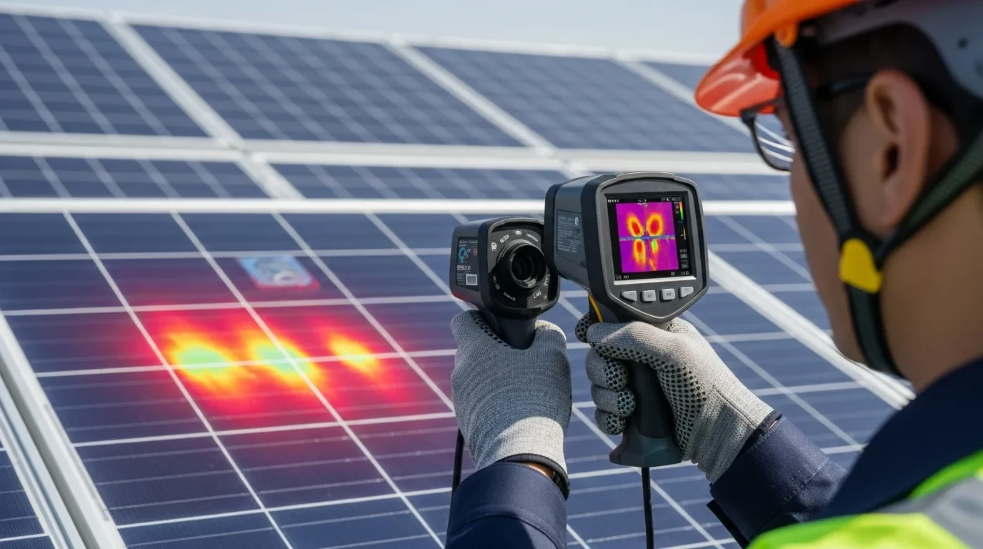
In the landscape of residential and commercial solar power, direct current (DC) electricity poses fundamentally different physical hazards than conventional alternating current (AC) grid power. While modern electrical safety codes have mastered AC arc-fault detection, solar arrays operate at continuous DC voltages ranging from 300V to over 600V in residential systems, and up to 1,500V in commercial installations.
When a high-voltage DC connection breaks, degrades, or corrodes under load, it creates an intense, self-sustaining electrical plasma arc.
Unlike an AC arc, which naturally collapses as voltage crosses zero every half-cycle, a DC arc has no zero-crossing point. Once air ionizes into conductive plasma between two conductors, the DC arc burns continuously as long as the sun illuminates the photovoltaic modules.
Reaching core plasma temperatures between 5,000°C and 10,000°C (9,000°F to 18,000°F)—hotter than the surface of the sun—a DC arc instantly vaporizes copper conductors, melts aluminum racking, shatters module backsheets, and ignites rooftop building membranes.
Understanding the physics of DC arc faults, the engineering mechanics of connector failure, and the signal processing algorithms defined in UL 1699B and mandated by NEC 690.11 is essential for designing resilient, fire-safe solar infrastructure.
Executive Summary: The Physics of Direct Current Arcing
The core distinction between AC and DC circuit interruptions dictates how electrical arcs ignite, sustain, and destroy balance-of-system hardware:
+-----------------------------------------------------------------------------------+
|               ELECTRICAL ARC DYNAMICS: AC vs HIGH-VOLTAGE DC                      |
+----------------------+-----------------------------+------------------------------+
| PARAMETER            | 120V / 240V AC (60 Hz)      | 400V - 600V DC (Solar Array) |
+----------------------+-----------------------------+------------------------------+
| Zero Crossings       | 120 per second              | ZERO (Continuous DC Bias)    |
| Self-Extinguishing   | Highly Probable (<8.3ms)    | IMPOSSIBLE (Self-Sustaining) |
| Plasma Temperature   | 2,000°C - 4,000°C           | 5,000°C - 10,000°C           |
| Arc Gap Stability    | Collapses during low phase  | Stretches 10mm to 50mm+      |
| Fault Current Draw   | Limited by supply impedance | Equal to or below Voc/Isc    |
| Overcurrent Trip     | Magnetic breaker trips fast | Fuse DOES NOT trip           |
| Primary Ignition     | Insulation abrasion/chafing | Connector cross-mate/crimp   |
+----------------------+-----------------------------+------------------------------+
Because an operating solar array is a current-limited DC generator, standard overcurrent protection devices (OCPDs)—such as DC breakers and string fuses—cannot detect or clear series arc faults. The arc burns at the exact operating current () of the string. Only specialized Arc-Fault Circuit Interrupters (AFCI) utilizing spectral frequency analysis can recognize the noise signature of ionized plasma and disconnect the array before rooftop ignition occurs.
Why DC Arcs Never Self-Extinguish: The Missing Zero-Crossing
To comprehend why DC arcs are destructive, one must examine the molecular transition of ambient air into an ionized plasma column.
Under normal conditions, air is an exceptional electrical insulator with a dielectric breakdown strength of approximately 3,000 Volts per millimeter (3 kV/mm). When two conductive surfaces physically separate while carrying electrical current, the contact resistance increases dramatically at the microscopic contact points right before physical disconnection.
This sudden restriction in conductor area creates extreme local current density, generating instantaneous Joulean heating (). The metallic contact points melt, vaporize, and emit metallic vapor.
The resulting electric field accelerates free electrons, which collide with nitrogen and oxygen molecules, ionizing them into a conducting plasma state:
+-----------------------------------------------------------------------------------+
|               THE DC ARC PLASMA SUSTAINMENT MECHANISM                             |
+-----------------------------------------------------------------------------------+
|                                                                                   |
|  [Intact Contact]  -->  [Micro-Separation]  -->  [Thermal Vaporization]           |
|         |                      |                           |                      |
|         v                      v                           v                      |
|   Low Resistance         Resistance Rises           Copper/Tin Vaporizes          |
|   Cold Joint             Local I²R Heating          Air Ionizes into Plasma       |
|                                                            |                      |
|                                                            v                      |
|  [Continuous Sun] <----------------------------- [Stable DC Plasma Column]        |
|  Current flows uninterrupted                     Voltage drop: 15V - 40V          |
|  No zero-crossing to deionize                    Core Temp: 5,000°C - 10,000°C    |
|  Air remains conductive plasma                   Adjacent combustibles ignite     |
|                                                                                   |
+-----------------------------------------------------------------------------------+
The AC De-Ionization Cycle vs DC Continuous Plasma
In a 60 Hz alternating current waveform:
- Voltage and current oscillate in a sine wave, passing through zero volts exactly 120 times every second (every 8.33 milliseconds).
- When the voltage passes through zero, power delivery ceases ().
- During this zero-crossing interval, the plasma cools, electrons recombine with positive ions, and the dielectric strength of the air gap restores itself. Unless the gap is microscopic or the re-applied voltage is exceptionally high, the arc self-extinguishes.
In a solar direct current circuit:
- The photovoltaic string supplies a non-pulsing, continuous unidirectional voltage potential.
- There are zero zero-crossings.
- The plasma column generates continuous thermal energy ().
- As long as the voltage drop across the gap exceeds the ionization threshold of the plasma (typically 15V to 30V per arc gap) and the solar panels supply current, the arc cannot self-extinguish.
The arc acts as a negative differential resistance device: as the plasma heats up, its electrical conductivity increases, allowing the arc to stretch across gaps of 10 to 50 millimeters while drawing full string current.
Series Arcs vs Parallel Arcs in Solar Arrays
In photovoltaic engineering, DC arc faults are classified into two categories based on their electrical topology: Series Arcs and Parallel Arcs. Each exhibits distinct electrical characteristics and requires different protection strategies.
+-----------------------------------------------------------------------------------+
|                   SERIES ARC vs PARALLEL ARC TOPOLOGY                            |
+-----------------------------------------------------------------------------------+
|                                                                                   |
|  SERIES ARC:                                                                      |
|  [PV Module (+)] ---> [PV Module] ---X--- [Inverter DC (+)]                      |
|                                  (Series Arc)                                     |
|  Current: Limited to string current (Imp). Cannot trip OCPD / fuses.              |
|  Mitigation: Open circuit (Stop Inverter / Trip Rapid Shutdown).                  |
|                                                                                   |
|  PARALLEL ARC:                                                                    |
|  [PV Module (+)] ----------------------------> [Inverter DC (+)]                  |
|          |                                            |                           |
|          +================ (Parallel Arc) ============+                           |
|          |                                            |                           |
|  [PV Module (-)] ----------------------------> [Inverter DC (-)]                  |
|                                                                                   |
|  Current: Supplied by all parallel strings. Can divide and bypass OCPD.           |
|  Mitigation: Short-circuiting the array or activating module-level disconnects.   |
|                                                                                   |
+-----------------------------------------------------------------------------------+
Series Arc Faults
A series arc fault occurs in-line with the electrical circuit conductor. It happens when an existing continuous circuit opens or develops high series resistance. Common locations include:
- A cracked solder ribbon inside a PV laminate.
- A corroded junction box terminal.
- An improperly seated or partially pulled MC4 quick-connector.
- A loose screw terminal in a DC combiner box or disconnect switch.
Electrical Signature
Because the arc is in series with the load, the total circuit impedance increases by the resistance of the arc ().
Consequently, the circuit current does not spike; it slightly drops.
If a string operates at 12 Amps and a 30V series arc develops, the inverter’s Maximum Power Point Tracker (MPPT) adjusts, and the string current settles at approximately 10 to 11.5 Amps.
Because standard string fuses are rated at 15A to 30A, a fuse will never trip during a series arc fault. To extinguish a series arc, the inverter must open its input DC switch or cease switching, collapsing the current flow to zero.
Parallel Arc Faults
A parallel arc fault occurs between two conductors of opposing electrical potential—between the positive DC rail and negative DC rail, or between a positive rail and metallic equipment ground (an arcing ground fault).
Electrical Signature
Parallel arcs represent a partial or complete short circuit across the array. The fault current is supplied by the photovoltaic modules and any parallel strings feeding into the same bus.
If three strings are paralleled without string fuses, or if an arc develops downstream of the combiner box, the fault current can reach 30 to 50 Amps of concentrated electrical power:
Ten kilowatts of concentrated electrical plasma creates an explosive thermal event. Within seconds, metal enclosures melt through, structural rafters catch fire, and the electrical fault can bridge across adjacent conduit runs.
Unlike series arcs, opening the inverter’s DC input does not extinguish a parallel arc, because the PV modules continue generating voltage and feeding the fault on the roof. Parallel arcs can only be cleared by module-level Rapid Shutdown (Module-Level Power Electronics / MLPE) or automated array shorting contactors.
The Failed Quick-Connector Epidemic: Cross-Mating and Poor Crimping
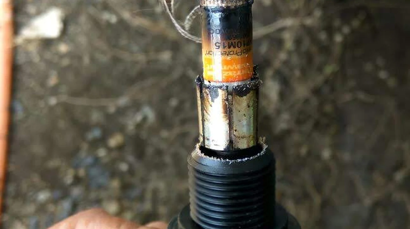
Forensic failure investigations conducted by national testing laboratories (such as Sandia National Laboratories and TÜV Rheinland) reveal that over 90% of solar DC arc-fault fires originate at DC quick-connectors (MC4 and compatible variants).
+-----------------------------------------------------------------------------------+
|               PRIMARY MECHANISMS OF SOLAR CONNECTOR FAILURE                       |
+--------------------------------------+--------------------------------------------+
| MECHANISM                            | PHYSICAL FAILURE PROGRESSION               |
+--------------------------------------+--------------------------------------------+
| Cross-Mating Incompatible Brands     | Dimensional mismatch (0.1mm) -> High      |
|                                      | contact resistance -> Thermal runaway.     |
+--------------------------------------+--------------------------------------------+
| Open-Barrel Pliers Crimping          | Uneven compaction -> Gas voids -> Copper   |
|                                      | oxidation -> Hot spot ignition.            |
+--------------------------------------+--------------------------------------------+
| Missing Cable Gland Torque           | Water ingress -> Electrolytic corrosion -> |
|                                      | Tin plating degradation -> Series arc.     |
+--------------------------------------+--------------------------------------------+
| Mechanical Strain / Bending          | Pin retraction -> Spring finger fatigue -> |
|                                      | Intermittent micro-arcing under wind load. |
+--------------------------------------+--------------------------------------------+
The Myth of Solar Quick-Connector Cross-Compatibility
The single largest contributor to rooftop solar fires is the practice of cross-mating connectors from different manufacturers.
Installers often connect a factory-installed connector on a solar module (e.g., Amphenol H4, QC Solar, or Tonglin) with an aftermarket “MC4” connector made by Stäubli, or a generic knockoff purchased online.
While these connectors appear to mate mechanically and latch securely:
- Internal Tolerances Differ: The internal diameter of the male pin and female socket differs by 0.05mm to 0.25mm across manufacturers.
- Spring Finger Elasticity Differs: Stäubli Multi-Contact genuine MC4 connectors utilize a proprietary beryllium copper Multilam spring basket designed for uniform contact pressure. Cheap clones use stamped sheet tin or brass with low elastic limits.
- Thermal Expansion Coefficients Differ: As roof temperatures swing from -20°C in winter to +85°C on summer afternoons, dissimilar metals expand at different rates.
When mismatched connectors carry 10 to 15 Amps of DC current, contact resistance () rises from nominal (under 0.2 mΩ) to 50 mΩ or higher.
According to Joule’s First Law ():
Eighteen watts concentrated inside a sealed plastic enclosure measuring only 15mm in diameter heats the interior beyond 150°C.
The polycarbonate or PPO housing melts, the spring fingers lose their temper, contact resistance climbs further, and an active series arc ignites.
Regulatory Rule (NEC 690.33(C)): The National Electrical Code strictly mandates that mating connectors must be of the same manufacturer and exact model line. Cross-mating connectors from different brands—even if labeled “MC4 compatible”—is an explicit electrical code violation and invalidates UL listings.
Improper Field Crimping Mechanics
The second major cause of connector failure is field-crimping with incorrect tooling.
A genuine photovoltaic crimp connection requires a four-axis ratchet crimping tool fitted with precision-machined dies matching the exact gauge of the cable (typically 10 AWG or 12 AWG / 4mm² or 6mm²). The tool must compress the open-barrel copper terminal with calibrated force, achieving cold-welding:
    CORRECT CRIMP (Cold-Weld):         POOR CRIMP (Pliers/Generic Die):
       .-----------------.                    .-----------------.
      /   .-----------.   \                  /    .         .    \
     |   /  o o o o o  \   |                |    / o o   o o \    |  <-- Gas Voids
     |  |  o o o o o o  |  |                |   |  o   o   o  |   |  <-- High Resistance
      \  \  o o o o o  /  /                  \   \   o   o   /   /   <-- Moisture Penetration
       '-----------------'                    '-----------------'
    100% Solid Gas-Tight Core               Loose Strands & Oxidation
When an installer uses generic wire strippers, slip-joint pliers, or uncalibrated crimpers:
- Strands are left uncompressed, creating micro-air gaps (gas voids).
- Atmospheric oxygen and humidity oxidize the exposed copper strands into copper oxide (), which is a semi-conductor.
- Under heavy midday electrical current, the contact undergoes thermal runaway until the terminal carbonizes and arcing initiates.
Arc Fault Standards and Electrical Safety: How Modern AFCI Detection Algorithms Work
To prevent arc-induced fires, NEC 690.11 mandates that all photovoltaic systems operating on or in buildings at 80 Volts DC or higher must include a listed DC Arc-Fault Circuit Interrupter (AFCI).
The functional testing and performance criteria for solar AFCI systems are governed by UL 1699B (Standard for Photovoltaic (PV) DC Arc-Fault Circuit Protection).
+-----------------------------------------------------------------------------------+
|               UL 1699B AFCI DETECTION AND MITIGATION WORKFLOW                     |
+-----------------------------------------------------------------------------------+
|                                                                                   |
|  [PV Array DC Current + High-Frequency Noise]                                     |
|         |                                                                         |
|         v                                                                         |
|  [Toroidal Current Transformer (CT) Sensor]                                       |
|         |                                                                         |
|         v                                                                         |
|  [Analog Bandpass Filter (10 kHz - 100 kHz)]                                      |
|         |                                                                         |
|         v                                                                         |
|  [High-Speed Analog-to-Digital Converter (ADC)]                                   |
|         |                                                                         |
|         v                                                                         |
|  [Digital Signal Processor (DSP) - FFT Spectral Analysis]                         |
|         |                                                                         |
|         +---> Is Noise Broad-Spectrum "Pink Noise"?                               |
|         |     (Continuous across multiple frequency bins)                         |
|         |                                                                         |
|         +---> Does Energy Exceed Cumulative Energy Threshold?                     |
|         |                                                                         |
|         +---> Does Signature Persist for >200ms?                                  |
|         |                                                                         |
|         v                                                                         |
|  [VERIFIED ARC FAULT TRIGGER]                                                     |
|         |                                                                         |
|         +---> Inverter Shuts Down Gate Drives within 2.0 Seconds (NEC 690.11)    |
|         +---> Inverter Opens DC Contactor / Isolator                              |
|         +---> System Latches Fault (Requires Manual Reset)                        |
|                                                                                   |
+-----------------------------------------------------------------------------------+
Digital Signal Processing (DSP) Architecture
A pure DC current waveform is flat and featureless. When an electrical arc burns, the chaotic, turbulent motion of ionized gas molecules creates high-frequency fluctuations in the current waveform, known as broadband 1/f noise (pink noise).
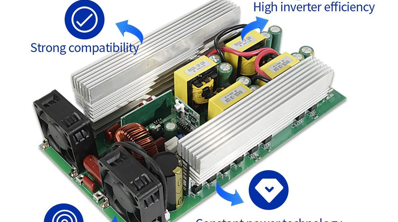
Modern inverters (such as SolarEdge, Enphase, Fronius, SMA, Sol-Ark, and Victron) incorporate dedicated AFCI hardware:
- High-Frequency Current Transformer: A specialized magnetic core sensor sits on the positive or negative DC bus, measuring AC ripple current up to several hundred kilohertz.
- Analog Bandpass Filtering: The raw signal passes through analog active filters configured to isolate frequencies between 10 kHz and 100 kHz (the primary spectral band for photovoltaic plasma arcs). Frequencies below 10 kHz are rejected to eliminate 60Hz/120Hz AC grid ripple.
- Fast Fourier Transform (FFT): The DSP breaks the filtered signal into narrow frequency bins in real time.
- Spectral Energy Integration: Unlike switching noise, which produces sharp spikes at discrete, predictable harmonic frequencies (e.g., 20 kHz, 40 kHz, 60 kHz), a true arc fault produces continuous, elevated energy across every bin in the entire 10 kHz to 100 kHz spectrum.
Safety Standard Clearing Time Requirements
Under UL 1699B Type 1 specifications:
- The AFCI detector must detect an arc of 300 Watts or greater (e.g., 30V at 10A).
- The system must extinguish the arc and de-energize the circuit within 2.0 seconds of initiation.
- The system must remain latched in an error state. Automatic self-clearing or unattended auto-restart is prohibited by NEC 690.11 to prevent an unattended inverter from repeatedly restriking an active rooftop arc.
Diagnosing Nuisance Tripping: Inverter Switching Noise vs True Arc Signatures
While AFCI technology is crucial for fire safety, early implementations earned a reputation for nuisance tripping—falsely detecting arc faults and shutting down solar arrays on clear, sunny days.
Understanding how to differentiate between inverter switching noise, external electromagnetic interference (EMI), and genuine arc faults is a vital skill for solar technicians and engineers.
+-----------------------------------------------------------------------------------+
|               FFT SPECTRAL COMPARISON: ARC FAULT vs INVERTER NOISE                |
+-----------------------------------------------------------------------------------+
|                                                                                   |
|  TRUE DC ARC FAULT (Continuous Broadband Pink Noise):                             |
|  Amplitude |                                                                      |
|            |  ~~~~~~~~~~~~~~~~~~~~~~~~~~~~~~~~~~~~~~~~ (Elevated broadband noise) |
|            |__________________________________________                            |
|             10kHz   25kHz   40kHz   55kHz   70kHz   100kHz                        |
|                                                                                   |
|  INVERTER MPPT / PWM SWITCHING NOISE (Discrete Harmonics):                        |
|  Amplitude |                                                                      |
|            |    |              |              |         (Narrow harmonic spikes)  |
|            |    |              |              |         (Floor remains quiet)     |
|            |____|______________|______________|_______                            |
|             10kHz (16kHz)   (32kHz)        (64kHz)  100kHz                        |
|                                                                                   |
+-----------------------------------------------------------------------------------+
Common Sources of Nuisance AFCI Tripping
- Parallel Conductor Crosstalk: When multiple DC string homeruns share the same metallic conduit over long distances, high-frequency capacitive and inductive coupling occurs between strings. If one string experiences minor MPPT ripple, it can couple into an adjacent string and trigger its AFCI detector.
- Inverter Switch-Mode Power Supply (SMPS) Harmonics: Inverters utilize silicon-carbide (SiC) or IGBT transistors switching at 16 kHz to 64 kHz to perform MPPT tracking. If internal DC filtering capacitors dry out or degrade, switching ripple bleeds onto the DC bus, mimicking an arc.
- External Radio Frequency Interference (RFI): Nearby high-power radio transmitters, ham radio antennas, variable frequency motor drives (VFDs), or unshielded electric fence chargers can induce high-frequency RF currents into long, unshielded rooftop PV wiring loops.
- Degraded Rapid Shutdown Transmitters: In rapid shutdown systems using Power Line Communication (PLC)—such as SunSpec-compliant transmitters—faulty signal transmitters or missing core inductors can create chaotic line reflections that fool the AFCI DSP.
Step-by-Step Field Diagnostic Workflow for AFCI Trips
When an inverter trips on a DC Arc-Fault code (e.g., “AFCI Fault - Manual Lockout”):
+-----------------------------------------------------------------------------------+
|                  SYSTEMATIC AFCI FIELD DIAGNOSTIC SEQUENCE                        |
+-----------------------------------------------------------------------------------+
|                                                                                   |
|  STEP 1: DO NOT BLINDLY RESET THE INVERTER                                       |
|  Restriking an active series arc can ignite smoldering roof materials.            |
|                                                                                   |
|  STEP 2: ISOLATE AND DISCONNECT                                                   |
|  Open AC disconnect. Open DC disconnect. Lock out / Tag out.                      |
|                                                                                   |
|  STEP 3: OPEN-CIRCUIT VOLTAGE (Voc) BENCHMARKING                                  |
|  Measure Voc of each string using a 1,000V CAT III DMM.                          |
|  Verify Voc matches calculated module specifications within ±2%.                   |
|                                                                                   |
|  STEP 4: INSULATION RESISTANCE (MEGGER) TEST                                      |
|  Apply 1,000V DC between DC (+) to Ground, and DC (-) to Ground.                   |
|  Target: >50 Megohms. If <1 Megohm, locate ground fault insulation tear.          |
|                                                                                   |
|  STEP 5: THERMAL IMAGING UNDER FULL SUN (>700 W/m²)                               |
|  Re-energize under clear sky. Scan every MC4 connector, combiner box, and         |
|  fuse holder with an IR camera (FLIR). Any junction >15°C above ambient is        |
|  an imminent arc hazard.                                                          |
|                                                                                   |
|  STEP 6: CONNECTOR TENSION AND PULL-TEST                                          |
|  Gently tug each connector pairing. Verify the locking tabs are fully seated      |
|  and internal pins have not pushed back into the plastic housing.                 |
|                                                                                   |
+-----------------------------------------------------------------------------------+
Complete Solar DC Arc-Fault Commissioning and Inspection Checklist
To guarantee that a commercial or residential solar installation remains completely free of DC arc hazards over a 25-year design lifespan, execute this rigorous commissioning checklist:
+-----------------------------------------------------------------------------------+
|          SOLAR DC ARC-FAULT COMMISSIONING AND HARDENING PROTOCOL                  |
+---+-------------------------------------------------------------------------------+
|   | 1. CONNECTOR SPECIFICATION AND COMPATIBILITY                                  |
| [ ] All connectors throughout the array are 100% original manufacturer matched.  |
| [ ] Zero cross-mating between different brands (No "MC4 compatible" substitutes). |
| [ ] All connectors rated for system maximum voltage (1,000V or 1,500V DC).       |
+---+-------------------------------------------------------------------------------+
|   | 2. MECHANICAL CRIMP INTEGRITY                                                 |
| [ ] Factory-calibrated ratchet crimp tool with matching manufacturer die set used.|
| [ ] Calibrated pull-test verified on sample crimps (minimum 310 N / 70 lbf).      |
| [ ] Cable glands torqued to manufacturer specification with specialized wrenches. |
+---+-------------------------------------------------------------------------------+
|   | 3. CONDUCTOR ROUTING AND STRAIN RELIEF                                        |
| [ ] Array wiring secured with 90-degree UV-resistant stainless steel wire clips.  |
| [ ] Minimum bend radius maintained (at least 4x to 6x cable outer diameter).      |
| [ ] Conductors protected against sharp edges of solar racking and roof flashing.  |
| [ ] Wiring loops minimized to prevent electromagnetic induction from lightning.   |
+---+-------------------------------------------------------------------------------+
|   | 4. ELECTRICAL TESTING AND VERIFICATION                                        |
| [ ] Insulation Resistance (Megger) tested at 1,000V DC (>50 MΩ threshold).        |
| [ ] Short-circuit current (Isc) tested under steady irradiance with DC clamp meter.|
| [ ] Inverter UL 1699B self-test executed via firmware diagnostics.                |
| [ ] Full thermal imaging audit completed under full load (>700 W/m² irradiance).  |
+---+-------------------------------------------------------------------------------+
|   | 5. RAPID SHUTDOWN AND EMERGENCY CONTROLS                                      |
| [ ] Rapid Shutdown Initiator (RSI) tested and verified (<30V within 30 seconds).  |
| [ ] Module-level power electronics (optimizers/microinverters) firmware updated.  |
| [ ] Clear warning labeling affixed per NEC 690.56(C) on main electrical panel.    |
+---+-------------------------------------------------------------------------------+
By engineering solar arrays with original factory-matched connectors, precision-calibrated ratchet crimping, generous wire strain relief, and modern UL 1699B digital signal processing AFCI inverters, off-grid and grid-interactive solar installations can operate at peak thermodynamic efficiency while completely eliminating the risk of catastrophic rooftop DC electrical fires.