When designing a rooftop photovoltaic installation, electrical engineers and solar contractors often expend enormous energy modeling cell temperature coefficients, inverter clipping thresholds, and string voltage open-circuit calculations. Yet one of the most frequent causes of failed electrical inspections, melted wire insulation, and catastrophic commercial rooftop fires occurs inside an ordinary pipe: rooftop electrical conduit.
Unlike wiring installed inside conditioned building walls or ventilated crawlspaces, electrical conduit installed across a building roof exists in an unyielding thermal microclimate. Dark composite asphalt shingles, modified bitumen, and black EPDM single-ply membranes absorb vast amounts of solar radiation, transforming the roof deck into an infrared radiative heat radiator. Concurrently, solar conductors operating near their continuous current limits generate internal resistive heat (), while the metal or plastic conduit walls trap air in a sealed greenhouse cylinder.
If an installer selects wire gauge based solely on standard room-temperature ampacity tables, the actual continuous current capacity of the conductors can plummet by forty to sixty percent under summer sun.
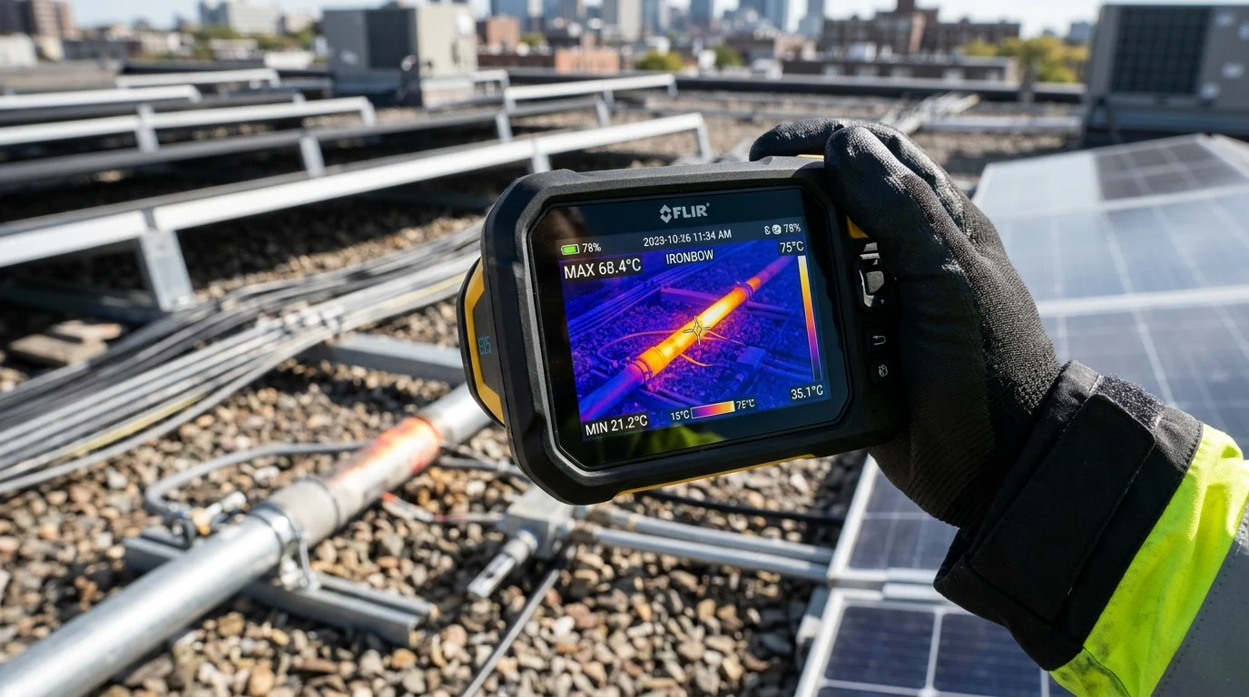
This engineering guide investigates the thermodynamic physics of rooftop solar conduit, breaks down the mathematical equations governing ambient temperature corrections and conductor bundling adjustments, analyzes real-world FLIR thermal radiometry scans, and provides structural sizing protocols for thermal expansion joints.
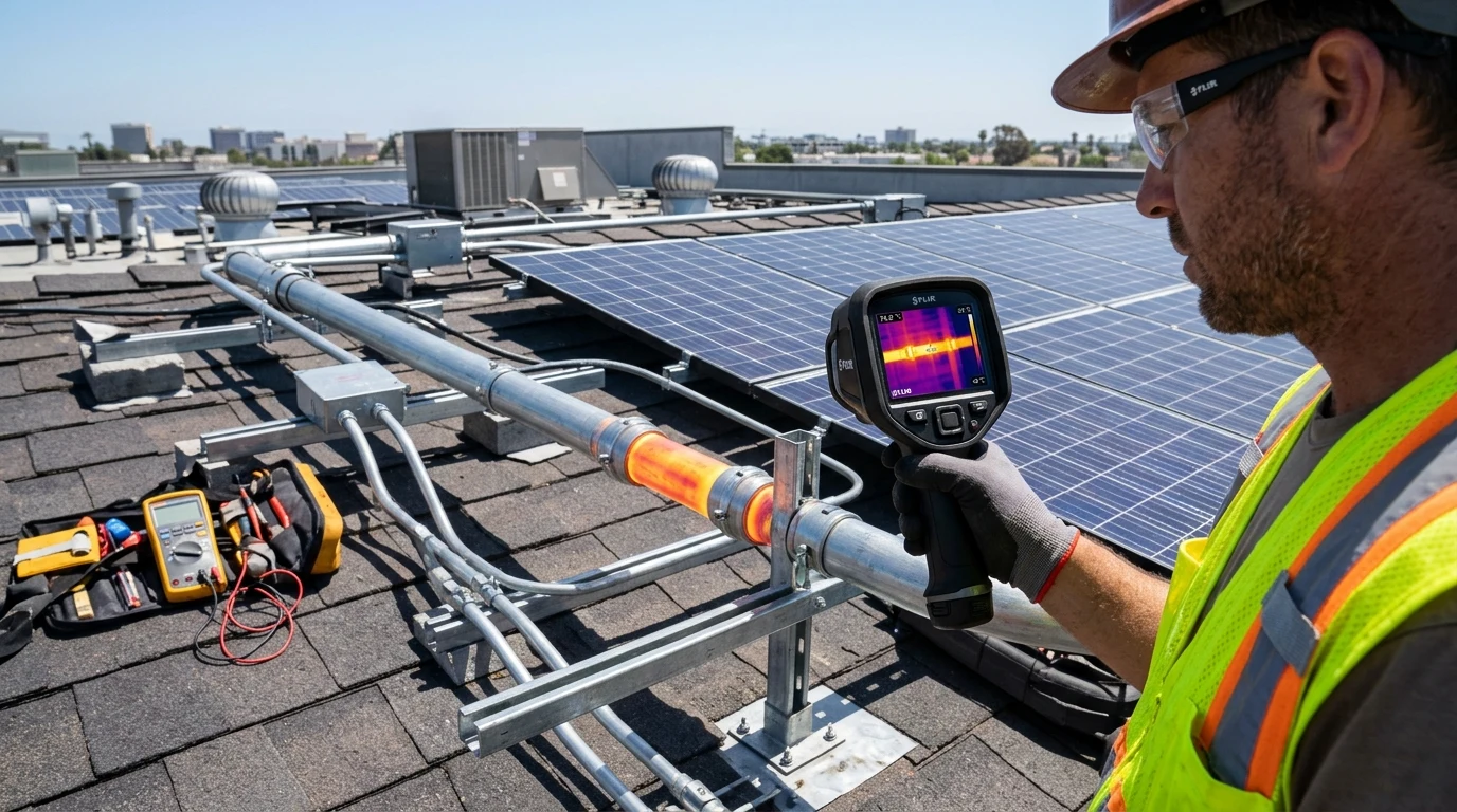
Executive Summary: The Physics of Solar Rooftop Thermal Traps
Electrical conductors are rated for ampacity based on the maximum continuous temperature their polymer insulation jacket can withstand before suffering chemical depolymerization, plasticizer outgassing, and dielectric breakdown.
Standard commercial and residential solar building wires—predominantly THHN / THWN-two and specialized USE-two / PV Wire—incorporate cross-linked polyethylene (XLPE) or heat-resistant thermoplastic insulation rated for a maximum operating temperature:
In standard electrical engineering handbooks, conductor ampacities are tabulated at a normalized ambient reference temperature:
When conduit is installed outdoors on a building roof exposed to direct sunlight, the internal air temperature () is determined by an energy balance between multiple heat transfer mechanisms:
+------------------------------------------------------------------------------------+
|               THERMODYNAMIC HEAT BALANCE INSIDE ROOFTOP CONDUIT                    |
+------------------------------------------------------------------------------------+
|                                                                                    |
|  [ Solar Radiation (q_solar) ] ========> Direct Irradiance on Conduit Shell        |
|  [ Roof Re-Radiation ]       ========> Infrared Blackbody Flux from Dark Shingles  |
|  [ Internal Wire Heat ]      ========> Joule Resistive Dissipation (I^2 * R)       |
|                                                                                    |
|                                      ||                                            |
|                                      \/                                            |
|  [ Sealed Air Space Inside Conduit ] ==> Trapped Heat: Reaches 65°C to 75°C!       |
|                                      ||                                            |
|                                      \/                                            |
|  [ Wire Insulation Degradation ]     ==> Drastic Ampacity Collapse (Over 50% Drop) |
|                                                                                    |
+------------------------------------------------------------------------------------+
Because air circulation inside conduit is virtually zero, stagnant air functions as a thermal insulator rather than a cooling medium. As a result, internal conduit temperatures routinely reach thirty to forty degrees Celsius above ambient air temperature, severely compressing the allowable thermal margin between the conduit environment and the wire insulation ceiling.
Mathematical Framework of Ambient Thermal De-Rating and Conduit Solar Gain
Determining the true, safe ampacity of a solar conductor requires applying rigorous mathematical correction factors established by National Electrical Code (NEC) Section 310.
Solar Radiation Absorption and Ashrae Design Temperature Baselines
Conduit de-rating cannot be calculated using average annual temperatures; it must be engineered against the two-percent annual design temperature published by the American Society of Heating, Refrigerating and Air-Conditioning Engineers (ASHRAE). The two-percent design temperature represents the ambient outdoor temperature that is exceeded for only two percent of the hours in the hottest summer months (typically thirty-five to forty-two degrees Celsius across sunny geographic regions).
When sunlight strikes a conduit surface, radiation absorption depends upon the material emissivity and surface solar absorptance ():
- Galvanized Steel Electrical Metallic Tubing (EMT): Exhibits low solar absorptance (), reflecting a significant portion of incoming visible radiation.
- Polyvinyl Chloride (PVC) Rigid Non-Metallic Conduit: Exhibits higher solar absorptance (), absorbing greater thermal energy under identical irradiance conditions.
Conduit Height Above Roof Surface and Microclimatic Airflow Dynamics
The vertical distance between the bottom of the conduit and the roof surface () is the single most critical geometric parameter controlling conduit temperature.
Directly at the roof surface (), stagnant air forms a boundary layer where thermal conduction from superheated asphalt shingles dominates. As conduit is elevated above the roof deck on structural strut channels or engineered rubber support blocks, ambient breeze creates turbulent convective heat transfer beneath the pipe:
+------------------------------------------------------------------------------------+
|                 ROOFTOP CONDUIT TEMPERATURE ADDER PROFILE                          |
+------------------------------------------------------------------------------------+
|  CLEARANCE HEIGHT ABOVE ROOF (h)     HEAT ADDER ABOVE AMBIENT   TYPICAL INTERNAL T |
+------------------------------------------------------------------------------------+
|  Resting directly on roof (0 in)     +33°C (+60°F)              71°C (160°F)       |
|  Under 0.5 inches (0 to 1/2 in)      +22°C (+40°F)              60°C (140°F)       |
|  0.5 inches to 3.5 inches            +17°C (+30°F)              55°C (131°F)       |
|  3.5 inches to 12.0 inches           +14°C (+25°F)              52°C (126°F)       |
|  Above 36.0 inches (High Stanchion)  +0°C (Ambient Air Baseline)38°C (100°F)       |
+------------------------------------------------------------------------------------+
Elevating conduit at least three and a half inches above the roof deck lowers peak internal temperatures by fifteen to twenty degrees Celsius compared to conduit resting directly on roof shingles.
Ampacity Correction Factors and Dielectric Insulation Temperature Ceilings
The allowable ampacity of a conductor under elevated ambient temperature is governed by the classical Neher-McGrath equation, formalized in NEC Table 310.15(B)(1):
Where:
- = Base ampacity from standard tables (e.g. NEC Table 310.16)
- = Conductor temperature rating ()
- = Total effective operating temperature ()
- = Standard reference temperature ()
- = Temperature Correction Factor
+------------------------------------------------------------------------------------+
|            TEMPERATURE CORRECTION MULTIPLIERS (FOR 90°C RATED INSULATION)         |
+------------------------------------------------------------------------------------+
|  EFFECTIVE CONDUIT TEMPERATURE       CORRECTION FACTOR (C_T)    AMPACITY IMPACT    |
+------------------------------------------------------------------------------------+
|  26°C to 30°C (78°F to 86°F)         1.00                       100% (No De-rating)|
|  36°C to 40°C (96°F to 104°F)        0.91                       91% Capacity       |
|  46°C to 50°C (114°F to 122°F)       0.82                       82% Capacity       |
|  56°C to 60°C (132°F to 140°F)       0.71                       71% Capacity       |
|  66°C to 70°C (150°F to 158°F)       0.58                       58% Capacity       |
|  71°C to 80°C (160°F to 176°F)       0.41                       41% Capacity       |
|  Over 80°C (Over 176°F)              0.00                       Unusable           |
+------------------------------------------------------------------------------------+
Notice that when effective conduit temperature enters the sixty-six to seventy degree range, the conductor’s current-carrying capacity is reduced by over forty percent.
Multiple Conductor Bundling De-Rating and Mutual Inductive Heating
When multiple photovoltaic strings are routed from a solar array to an inverter or combiner box, installers frequently pull several string circuits through a single shared conduit run. This introduces a second, compounding de-rating requirement: Conductor Bundling Adjustment.
Current-Carrying Conductor Count and Continuous Load Multipliers
Every energized DC conductor carries electrical current, generating heat through internal resistance:
When conductors are isolated in open air, heat dissipates freely via radiation and ambient convection. However, when multiple conductors are bundled closely inside a confined conduit envelope, the interior conductors are thermally insulated by surrounding wires:
+------------------------------------------------------------------------------------+
|             CONDUIT CONDUCTOR BUNDLE CROSS-SECTION AND THERMAL TRAP                |
+------------------------------------------------------------------------------------+
|                                                                                    |
|                      /-------------------------\                                   |
|                     /      Conduit Shell        \                                  |
|                    |     [O]       [O]     [O]   |                                 |
|                    |   Wire 1    Wire 2  Wire 3  |                                 |
|                    |         \   /     \         |                                 |
|                    |     [O]   [X]     [O]       |  [X] = Core Trapped Conductor   |
|                    |   Wire 4  Wire 5  Wire 6    |        Heat cannot escape!      |
|                    |     [O]       [O]     [O]   |                                 |
|                     \  Wire 7    Wire 8  Wire 9 /                                  |
|                      \-------------------------/                                   |
|                                                                                    |
+------------------------------------------------------------------------------------+
The center wires cannot transfer heat directly to the conduit wall, creating a thermal core that elevates the internal temperature of the entire assembly.
Under NEC Section 310.15(C)(1), when more than three current-carrying conductors are installed in a raceway or cable, the allowable ampacity must be multiplied by an Adjustment Factor ():
+------------------------------------------------------------------------------------+
|               CONDUCTOR BUNDLING ADJUSTMENT FACTORS (NEC TABLE 310.15(C)(1))       |
+------------------------------------------------------------------------------------+
|  CURRENT-CARRYING CONDUCTORS         BUNDLE ADJUSTMENT FACTOR (A_B)                |
+------------------------------------------------------------------------------------+
|  One to Three Conductors             1.00 (No Bundling Penalty)                    |
|  Four to Six Conductors (2-3 Strings)0.80 (20% Reduction)                          |
|  Seven to Nine Conductors (4 Strings)0.70 (30% Reduction)                          |
|  Ten to Twenty Conductors            0.50 (50% Reduction)                          |
|  Twenty-One to Thirty Conductors     0.45 (55% Reduction)                          |
+------------------------------------------------------------------------------------+
In a direct current photovoltaic circuit, both the positive and negative conductors are current-carrying. Equipment grounding conductors (green insulated or bare copper) do not carry continuous current and are excluded from the bundling count.
Joule Heating and Heat Dissipation Through Conduit Wall Boundaries
The true final allowable ampacity of any rooftop solar conductor () is the mathematical product of the base table ampacity, the ambient temperature correction factor, and the bundle adjustment factor:
Consider a practical engineering calculation benchmarking a standard residential rooftop installation:
- Conductor: Number ten AWG copper THWN-two
- Base Ampacity (Table 310.16 at 90°C): Forty amperes ()
- Design Ambient Temperature: Thirty-eight degrees Celsius ()
- Conduit Elevation: One inch above roof ( roof adder)
- Total Operating Temperature:
- Circuit Architecture: Three series strings (six current-carrying conductors)
Calculating final derated continuous ampacity:
Under NEC Article 690.8, solar circuits must also carry a continuous duty safety margin of one hundred and twenty-five percent (). Therefore, the maximum allowable short-circuit current () of a solar string connected to this wire is:
If an installer attempts to route high-current commercial bifacial panels (generating fourteen to sixteen amperes short-circuit current) through a conduit containing four or five strings, the total continuous current will overwhelm the derated conductor, melting wire insulation and tripping circuit overcurrent devices.
Mechanical Thermal Expansion: Preventing Conduit Buckling and Weatherhead Shear
Temperature swings on a rooftop do not merely stress electrical insulation; they exert massive mechanical forces on the physical conduit assembly.
Coefficient of Linear Expansion: Metallic EMT vs Non-Metallic PVC
All solid materials expand when heated and contract when cooled according to their fundamental material Coefficient of Linear Thermal Expansion ():
Where:
- = Change in length (inches or millimeters)
- = Total length of conduit run
- = Coefficient of linear expansion
- = Maximum anticipated annual temperature delta ()
+------------------------------------------------------------------------------------+
|               MATERIAL THERMAL EXPANSION COMPARISON ACROSS 100°F DELTA             |
+------------------------------------------------------------------------------------+
|  CONDUIT MATERIAL          EXPANSION COEFFICIENT (α_L)  EXPANSION PER 100 FT (30M) |
+------------------------------------------------------------------------------------+
|  Steel EMT / RMC Conduit   0.0000065 in/in/°F           0.78 inches (20 mm)        |
|  Aluminum Rigid Conduit    0.0000128 in/in/°F           1.54 inches (39 mm)        |
|  Schedule 40 / 80 PVC Pipe 0.0000300 in/in/°F           3.60 inches (91 mm)        |
+------------------------------------------------------------------------------------+
Notice that PVC conduit expands nearly five times more than steel EMT. On a one-hundred-foot rooftop run experiencing an annual temperature differential of one hundred and twenty degrees Fahrenheit (between zero degrees Fahrenheit in mid-winter and one hundred and twenty degrees Fahrenheit inside superheated summer conduit), a rigid PVC run will expand and contract by over four point three inches.
Without engineered mechanical expansion joints, an expanding PVC run will buckle upward like an accordion, tear roof mounting anchors out of roof trusses, or shear off at building weatherhead penetrations, allowing rainwater to flood electrical panels below.
+------------------------------------------------------------------------------------+
|             CONDUIT BUCKLING FAILURE UNDER UNMITIGATED THERMAL EXPANSION           |
+------------------------------------------------------------------------------------+
|                                                                                    |
|  WINTER BASELINE (Cold / Contracted):                                              |
|  [ Anchor A ] ---------------------------------------------------- [ Anchor B ]   |
|                                                                                    |
|  SUMMER EXPANSION (Hot / Unrelieved):                                              |
|                     /\  <==== Severe upward buckling and bowing!                   |
|                    /  \       Pulls roof screws out of decking!                    |
|  [ Anchor A ] ----/    \------------------------------------------ [ Anchor B ]   |
|                                                                                    |
+------------------------------------------------------------------------------------+
Expansion Fitting Placement and Structural Anchor Sizing Protocols
To absorb linear movement safely, electrical engineers specify Telescoping Conduit Expansion Fittings:
- Expansion Joint Travel Capacity: Standard industrial expansion couplings provide two to eight inches of linear telescoping travel.
- Expansion Joint Positioning: Mount the barrel of the expansion fitting solidly to an anchor support, allowing the internal piston sleeve to slide freely through downstream guide supports.
- Bonding Jumpers for Metallic Systems: Steel EMT expansion fittings disrupt the continuous mechanical metal path required for equipment grounding. An external braided copper bonding jumper strap must be clamped across the expansion joint using approved grounding lugs to maintain a continuous, low-impedance ground-fault return path.

Complete Solar Rooftop Conduit Engineering and Ampacity Checklist
To guarantee absolute compliance with National Electrical Code mandates and prevent rooftop thermal failures, certified electrical contractors execute this step-by-step sizing protocol:
+------------------------------------------------------------------------------------+
|             ENGINEERING SIZING CHECKLIST: ROOFTOP SOLAR CONDUIT                    |
+------------------------------------------------------------------------------------+
|  STEP  DESIGN STAGE        ACTION ITEM                         SPECIFICATION       |
+------------------------------------------------------------------------------------+
|  01    Site Microclimate   Determine ASHRAE Ambient Baseline   Use 2% Summer Max   |
|                            Consult ASHRAE climatic tables for  Design temperature  |
|                            the specific project geographic     must be documented  |
|                            coordinates.                        in permit package.  |
|                                                                                    |
|  02    Rooftop Geometry    Specify Minimum Stanchion Height    h >= 3.5 Inches     |
|                            Elevate conduit at least 3.5 inches Elevating conduit   |
|                            above roof deck using UV-rated strutreduces heat adder  |
|                            supports with EPDM cushion pads.    from 33°C to 14°C.  |
|                                                                                    |
|  03    Thermal De-Rating   Calculate Combined Derating Factor  C_T * A_B           |
|                            Multiply Table 310.16 base ampacity Ensure derated      |
|                            by ambient temperature factor (C_T) ampacity exceeds    |
|                            and bundling factor (A_B).          125% of string Isc. |
|                                                                                    |
|  04    Raceway Sizing      Verify Conduit Jam Ratio & Fill     Max 40% Fill Ratio  |
|                            Ensure total conductor area does notNever pull more than|
|                            exceed 40% of internal conduit area;eight conductors in|
|                            avoid jam ratios between 2.8 & 3.2. a single 3/4" pipe. |
|                                                                                    |
|  05    Expansion Math      Calculate Annual Length Delta       Install Joint if    |
|                            Compute total expansion (L * α * ΔT)expansion exceeds   |
|                            for metallic EMT and PVC raceways.  0.25 inches total.  |
|                                                                                    |
|  06    Bonding Jumpers     Verify Ground Path Across Joints    UL 467 Certified    |
|                            Install braided copper bonding      Verify under 0.1 Ω  |
|                            straps across metallic telescoping  continuity across   |
|                            expansion fittings with hex lugs.   the expanded joint. |
+------------------------------------------------------------------------------------+
By engineering rooftop conduit as an integrated thermodynamic and mechanical system—elevating raceways off dark shingles, calculating compounded thermal and bundling de-rating multipliers, and installing copper-bonded expansion joints—solar engineers protect conductors from premature thermal aging and guarantee decades of safe, high-yield solar energy generation.