Potential-Induced Degradation (PID) represents one of the most insidious, financially devastating failure modes in modern photovoltaic engineering. Unlike localized shading, bypass diode failures, or hot-spot cell fractures—which trigger instantaneous MPPT current drops or visible thermal discoloration—PID operates as an electro-chemical stealth phenomenon. A multi-kilowatt rooftop or ground-mount array can silently surrender thirty to fifty percent of its cumulative energy yield over twenty-four to thirty-six months while showing zero physical damage under ambient visual inspection.
As residential string voltages escalated from traditional low-voltage configurations up to six hundred volts direct current, and commercial microgrids standardly operate at one thousand to fifteen hundred volts direct current, the electrostatic potential between solar cells and earth ground has multiplied exponentially. When paired with modern transformerless non-isolated inverters, this high potential creates relentless electrostatic fields that drive mobile metal cations directly into the silicon crystal lattice, creating microscopic electrical shunts across the solar cell PN junction.
This engineering guide dissects the atomic physics of PID, charts the precise electrochemistry of sodium ion drift through soda-lime front glass, reveals advanced field diagnostic methodologies using electroluminescence and thermal radiometry, and details the electrical commissioning of nighttime high-voltage anti-PID recovery systems.

Executive Summary: The Silent Power Loss in High-Voltage Solar Arrays
In an ideal photovoltaic module, electrical current generated by photon absorption flows strictly through the cell busbars, interconnect ribbons, and string conductors to the inverter power stage. In real-world field installations, however, the active semiconductor wafers are mechanically encapsulated between layers of Ethylene Vinyl Acetate (EVA), sealed behind a front sheet of soda-lime glass, backed by a polymer backsheet, and clamped inside an anodized aluminum perimeter frame.
Under National Electrical Code (NEC) mandates, the structural aluminum module frames, mounting rails, and steel racking must be solidly bonded to equipment ground for personnel safety and lightning surge dissipation. Consequently, the exterior aluminum frame is permanently anchored at zero volts earth potential:
In modern ungrounded transformerless inverter topologies—which utilize symmetrical high-frequency Pulse Width Modulation (PWM) switching—the negative direct current bus conductor operates at a deep negative potential relative to earth ground during daylight operation:
In a residential six hundred volt direct current string, modules positioned near the negative pole of the string operate under continuous negative potential biases between negative three hundred volts and negative six hundred volts relative to their grounded aluminum frames. In commercial one thousand volt strings, this negative potential reaches negative five hundred volts to negative one thousand volts.
+------------------------------------------------------------------------------------+
|                POTENTIAL-INDUCED DEGRADATION (PID) POTENTIAL PROFILE               |
+------------------------------------------------------------------------------------+
|  STRING POLARITY:   [ (+) Pole: +500V DC ] ------------> [ (-) Pole: -500V DC ]     |
|                                                                                    |
|  ALUMINUM FRAME:    [ Bonded Ground: 0V ] -------------> [ Bonded Ground: 0V ]     |
|                                                                                    |
|  ELECTRIC FIELD:    Minimal / Repelling                 High Negative Bias:        |
|  ION MIGRATION:     No Sodium Influx                    Aggressive Na+ Drift       |
|  MODULE HEALTH:     100% Rated Yield                    30% to 50% Shunt Loss      |
+------------------------------------------------------------------------------------+
This sustained potential difference creates a potent electrostatic gradient across the front glass and encapsulant layers. Driven by this electric field, trace alkali metal cations—predominantly sodium ()—drift out of the glass matrix, permeate the polymer encapsulant, and accumulate at the front surface and antireflective coating of the crystalline silicon cell, collapsing both the open-circuit voltage and fill factor of the module.
Electrochemistry of Potential-Induced Degradation: Sodium Ion Drift Physics
Understanding PID requires tracing the path of charge carriers across the multi-layer composite sandwich that protects solar cells from mechanical impact and environmental weathering.
Soda-Lime Glass Composition and Mobile Cation Migration
Photovoltaic front glass is manufactured from standard soda-lime silicate glass due to its exceptional optical transparency, mechanical rigidity, and low manufacturing cost. Soda-lime glass contains approximately fourteen percent sodium oxide () and trace amounts of calcium oxide () and magnesium oxide ():
In the glass amorphous network, sodium ions are non-covalently bound to non-bridging oxygen atoms. Because sodium ions possess a small ionic radius (approximately one hundred and two picometers) and a single positive elementary charge, their activation energy for hopping conduction through the silicate network is remarkably low:
When a high negative voltage bias is applied to the crystalline solar cell relative to the grounded glass frame, the resulting electric field (, where is the dielectric distance) exerts an electrostatic Lorentz force pulling positively charged sodium ions toward the negative potential of the solar cell.
        (+) Grounded Aluminum Frame (0V)
              |
              v
  [ Soda-Lime Front Glass ]  =======> High Na+ Concentration Reservoir
              |
              |  Electric Field Gradient (E-Field)
              v
  [ Ethylene Vinyl Acetate (EVA) Encapsulant ]
              |
              |  Na+ Ion Drift Accelerated by Heat & Humidity
              v
  [ Silicon Nitride Antireflective Coating (SiNx) ]
              |
              v
  [ Crystalline Silicon Cell (P-Type Base / N-Type Emitter) ] (-600V DC)
Ethylene Vinyl Acetate Encapsulant Permeability and Humidity Acceleration
The polymer encapsulant layer—most commonly Ethylene Vinyl Acetate (EVA)—serves as the primary dielectric barrier between the front glass and the silicon cell. Under standard ambient laboratory conditions (twenty-five degrees Celsius and dry air), high-grade EVA exhibits volume resistivity exceeding:
However, in field environments subject to elevated ambient temperatures and relative humidity (damp heat conditions), atmospheric water vapor permeates the module edges and backsheet. Moisture molecules chemically hydrolyze residual vinyl acetate groups within the EVA matrix, synthesizing trace acetic acid ():
Acetic acid dissociation releases hydronium ions, accelerating glass corrosion and drastically suppressing the dielectric volume resistivity of the EVA polymer by up to three orders of magnitude:
As electrical resistivity plummets, leakage current paths open between the front glass and the silicon cell surface. Elevated module operating temperatures (frequently reaching sixty to seventy-five degrees Celsius under summer sun) accelerate sodium ion mobility according to the Arrhenius relationship, multiplying drift velocity exponentially:
PN Junction Shunting and Surface Recombination Centers
Upon reaching the silicon cell front surface, mobile sodium ions encounter the silicon nitride () antireflection coating and the underlying phosphorus-doped N-type emitter layer. The accumulated positive sodium cations create two devastating electronic degradation mechanisms:
- Electrostatic Inversion and Surface Recombination: The dense accumulation of positive charges at the dielectric interface distorts the energy band structure of the underlying silicon, pinning the Fermi level and dramatically increasing surface recombination velocity (). Photogenerated electron-hole pairs recombine instantaneously at surface defect states before they can be separated by the internal junction field.
- Microscopic Stacking Fault Shunting: Driven by the severe electrostatic gradient, sodium ions penetrate along one-dimensional crystalline defects, crystal grain boundaries, and stacking faults across the shallow N-type emitter into the P-type silicon base. The concentrated sodium atoms create conductive metallic filaments that physically bridge the PN junction:
When shunt resistance collapses, the cell can no longer maintain voltage potential under illumination; current generated by unshaded portions of the cell recirculates internally through the sodium shunts, transforming the affected cells into passive parasitic loads.
Identifying Degradation in the Field: Diagnostics and Telemetry Signatures
Because PID develops without audible alarms, shattered glass, or inverter error codes, identifying degradation demands rigorous data auditing and specialized diagnostic instrumentation.
Electroluminescence Imaging and Honeycomb Thermal Patterns
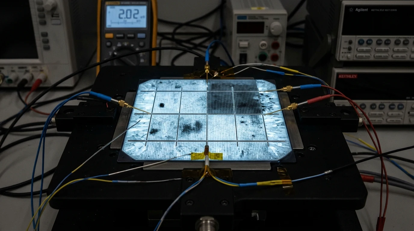
The gold standard for definitive PID diagnosis is Electroluminescence (EL) Imaging. In an EL test, technicians operate the solar array at night by injecting a forward-bias direct current (equal to the module rated short-circuit current, ) into the string using an external high-voltage direct current power supply.
Under forward bias, healthy silicon cells emit near-infrared photons (wavelength approximately one thousand one hundred and fifty nanometers) via band-to-band radiative recombination. A modified cooled silicon CCD or InGaAs short-wave infrared (SWIR) camera captures this luminescence:
- Healthy Solar Modules: Exhibit uniform, bright emission across every individual wafer square.
- PID-Stricken Solar Modules: Display a striking, unmistakable optical pattern: cells nearest the grounded aluminum perimeter frame appear pitch black or dark grey, having lost their radiative capability due to severe shunt paths. Cells toward the physical center of the laminate remain moderately luminous, creating a distinct “checkerboard” or “honeycomb” gradient.
+------------------------------------------------------------------------------------+
|               ELECTROLUMINESCENCE (EL) STRING DIAGNOSTIC SIGNATURE                 |
+------------------------------------------------------------------------------------+
|                                                                                    |
|  MODULE AT POSITIVE TERMINAL (+500V DC):                                           |
|  [ ■ ][ ■ ][ ■ ][ ■ ][ ■ ][ ■ ] -> Fully luminous, healthy, 0% shunt degradation   |
|  [ ■ ][ ■ ][ ■ ][ ■ ][ ■ ][ ■ ]                                                    |
|                                                                                    |
|  MODULE AT MID-POINT STRING (0V Reference):                                        |
|  [ ■ ][ ▧ ][ ■ ][ ▧ ][ ■ ][ ■ ] -> Mild edge darkening, under 5% yield drop        |
|  [ ▧ ][ ■ ][ ▧ ][ ■ ][ ▧ ][ ■ ]                                                    |
|                                                                                    |
|  MODULE AT NEGATIVE TERMINAL (-500V DC):                                           |
|  [ ░ ][ ░ ][ ░ ][ ░ ][ ░ ][ ░ ] -> Complete dark shunting along perimeter frame,    |
|  [ ░ ][ ▨ ][ ▨ ][ ▨ ][ ░ ][ ░ ] -> 45% power collapse, severe PID degradation     |
|                                                                                    |
+------------------------------------------------------------------------------------+
|  LEGEND: [ ■ ] = High Radiance (Healthy)   [ ░ ] = Zero Radiance (Shunted by PID)  |
+------------------------------------------------------------------------------------+
Thermal radiometry via high-resolution FLIR cameras yields a secondary diagnostic signature. Under daylight load operation, severely shunted cells exhibit elevated localized temperatures (frequently five to fifteen degrees Celsius hotter than adjacent healthy cells) because photogenerated power cannot exit the module and is dissipated internally as resistive heat.
Open-Circuit Voltage and Fill Factor Collapse
Solar monitoring platforms and high-speed telemetry loggers reveal PID through systematic divergence in string electrical parameters:
+------------------------------------------------------------------------------------+
|                    ELECTRICAL PARAMETER IMPACT UNDER PID STRESS                    |
+------------------------------------------------------------------------------------+
|  ELECTRICAL PARAMETER         HEALTHY MODULE     PID DEGRADED      PERCENT IMPACT  |
+------------------------------------------------------------------------------------+
|  Short-Circuit Current (Isc)  13.85 A            13.55 A           -2.1% (Minimal) |
|  Open-Circuit Voltage (Voc)   49.80 V            36.20 V           -27.3% (Severe) |
|  Fill Factor (FF)             78.5 %             51.2 %            -34.7% (Severe) |
|  Maximum Power (Pmax)         540.0 W            275.4 W           -49.0% (Critical|
|  Shunt Resistance (Rsh)       12,500 Ω           18 Ω              -99.8% (Collapse|
+------------------------------------------------------------------------------------+
Notice that short-circuit current () remains almost entirely intact; photon absorption and initial carrier generation are unimpeded. However, because shunt resistance has collapsed, the current-voltage (I-V) curve loses its square knee, collapsing maximum power voltage () and fill factor (). When string voltage sags below the inverter minimum MPPT tracking threshold during hot midday hours, the inverter drops the string entirely or throttles production catastrophically.
Prevention and Reversal: Anti-PID Nighttime Voltage Recovery
Unlike irreversible cell browning or silicon crack propagation, Potential-Induced Degradation is electrochemically reversible in standard P-type crystalline silicon modules if addressed before permanent electrochemical corrosion occurs.
Negative-Ground Topologies vs Virtual Neutral Offsetting
Historically, PID was virtually nonexistent in early commercial arrays that utilized centralized, low-frequency transformer-isolated inverters. In those legacy systems, installers solidly bonded the negative DC conductor to earth ground:
Because every solar cell operated at an equal or positive potential relative to the grounded frame, positive sodium ions were electrostatically repelled away from the cells toward the glass exterior, completely eliminating PID.
However, modern high-efficiency transformerless inverters (such as string inverters from SMA, Fronius, SolarEdge, Sungrow, and hybrid systems from Sol-Ark and EG4) prohibit solid DC grounding because non-isolated DC circuits share a common reference with the alternating current grid. Solidly grounding a DC conductor on a transformerless inverter creates a catastrophic short-circuit across the inverter input bridge.
To combat this without transformers, commercial inverter manufacturers developed Virtual Neutral Offsetting. During daylight operation, internal power electronics shift the DC bus potential electrostatically, ensuring the entire direct current string floats above zero volts ground potential throughout daylight generation hours.
+------------------------------------------------------------------------------------+
|               DAYLIGHT RUNTIME VS NIGHTTIME RECOVERY VOLTAGE REGIMES               |
+------------------------------------------------------------------------------------+
|  DAYLIGHT GENERATION (UNPROTECTED):                                                |
|  (+) Pole: +300V DC  <------- Reference: Ground (0V) -------> (-) Pole: -300V DC    |
|  Result: Negative pole cells suffer continuous sodium cation drift and shunting.   |
|                                                                                    |
|  NIGHTTIME ANTI-PID RECOVERY INJECTION:                                            |
|  Array Disconnected from Inverter Stage.                                           |
|  Anti-PID Box applies: +800V to +1000V DC between Array Conductors and Frame.     |
|  Result: Powerful reverse electrostatic field pulls Na+ ions back into glass.      |
+------------------------------------------------------------------------------------+
Nighttime Reverse High-Voltage Bias Injection
For existing arrays experiencing PID or systems using inverters without built-in voltage offsetting, the universal engineering solution is an Anti-PID Nighttime Recovery Device.
An Anti-PID controller is a specialized, micro-amperage high-voltage direct current power supply installed between the inverter DC disconnect switch and equipment ground. The system operates autonomously via string voltage sensing and optical irradiance telemetry:
- Daylight Inverter Disconnect: At sunset, when solar irradiance drops below five watts per square meter, the string inverter de-energizes its MPPT inputs and opens its internal direct current isolation contactors.
- Nighttime Bias Engagement: After a safety timeout verifying zero string generation and high insulation resistance, the Anti-PID controller closes high-voltage vacuum relays, connecting its internal regulated high-voltage DC generator across the photovoltaic array.
- Electrostatic Reversal Field: The recovery module applies a positive high-voltage direct current bias (typically positive five hundred to positive one thousand volts direct current, current-limited to under ten milliamperes for personnel safety) between the shorted solar conductors and the grounded equipment frame:
This intense reverse electrostatic field acts upon the trapped sodium ions within the silicon lattice. Over six to eight hours of darkness, the positive electric field electrostatically pulls the mobile cations out of the cell emitter, through the silicon nitride antireflective film, and back across the EVA encapsulant into the soda-lime glass reservoir.
        (+) Applied High-Voltage Positive Potential (+1000V DC)
              |
              v
  [ Silicon Solar Cell ]  =====> Repels Trapped Na+ Cations Electrostatically
              |
              |  Reverse Electric Field Forces Ion Migration
              ^
  [ EVA Polymer Layer ]
              ^
              |  Na+ Ions Drift Away from PN Junction Shunts
              |
  [ Front Soda-Lime Glass ]
              ^
              |
        (-) Grounded Aluminum Frame Reference (0V)
By morning, the microscopic conductive shunts across the PN junction have dissolved. Nominal shunt resistance () is restored, open-circuit voltage returns to original nameplate specification, and the string delivers full rated wattage when sunrise triggers the daytime disconnection sequence.

Complete Solar Array PID Prevention and Recovery Protocol
When designing new high-voltage photovoltaic systems or rehabilitating degraded strings in the field, certified solar engineers execute the following end-to-end commissioning checklist:
+------------------------------------------------------------------------------------+
|               ENGINEERING PROTOCOL: PID MITIGATION AND FIELD RECOVERY              |
+------------------------------------------------------------------------------------+
|  STEP  PHASE               ACTION ITEM                         SPECIFICATION       |
+------------------------------------------------------------------------------------+
|  01    Procurement         Specify Anti-PID Solar Modules      IEC 62804 Certified |
|                            Ensure modules pass 85°C / 85% RH                       |
|                            at 1000V/1500V bias for 96 hours with                   |
|                            power degradation under 5%.                             |
|                                                                                    |
|  02    Materials           Select High-Resistivity Polymers    POE vs Standard EVA |
|                            Demand Polyolefin Elastomer (POE)                       |
|                            encapsulants for ungrounded systems;                    |
|                            POE volume resistivity is 100x EVA                      |
|                            and resists water vapor hydrolysis.                     |
|                                                                                    |
|  03    Inverter Selection  Audit Inverter Grounding Topologies Floating Bus Shift   |
|                            Confirm inverter firmware supports                      |
|                            dynamic virtual neutral shifting or                     |
|                            internal nighttime anti-PID bias.                       |
|                                                                                    |
|  04    Field Commissioning Install Anti-PID Dedicated Hardware NEMA 4X DIN Enclosed|
|                            Mount industrial Anti-PID box                           |
|                            adjacent to DC combiner; route double-                  |
|                            insulated 1000V conductors to terminal                  |
|                            blocks and connect 10 AWG copper ground                 |
|                            to master earth electrode.                              |
|                                                                                    |
|  05    Safety Interlocks   Verify Ground Fault Diagnostics     GFDI / Insulation R |
|                            Ensure Anti-PID system automatically                    |
|                            inhibits voltage injection if string                    |
|                            isolation resistance drops under 50 kΩ.                 |
|                                                                                    |
|  06    Post-Fix Validation Electroluminescence String Audit    96-Hour Night Trial |
|                            Conduct baseline EL imaging before                      |
|                            treatment; run nighttime recovery for                   |
|                            two weeks; re-image to confirm complete                 |
|                            restoration of dark shunted wafers.                     |
+------------------------------------------------------------------------------------+
By engineering PID resilience into the hardware specification phase—mandating IEC 62804 certified modules, utilizing moisture-impermeable Polyolefin Elastomer (POE) encapsulants, and deploying automated nighttime reverse-bias recovery circuits—off-grid homesteaders, commercial operators, and microgrid engineers ensure their high-voltage solar arrays deliver maximum kilowatt-hour yields across their full twenty-five to thirty-year design life.