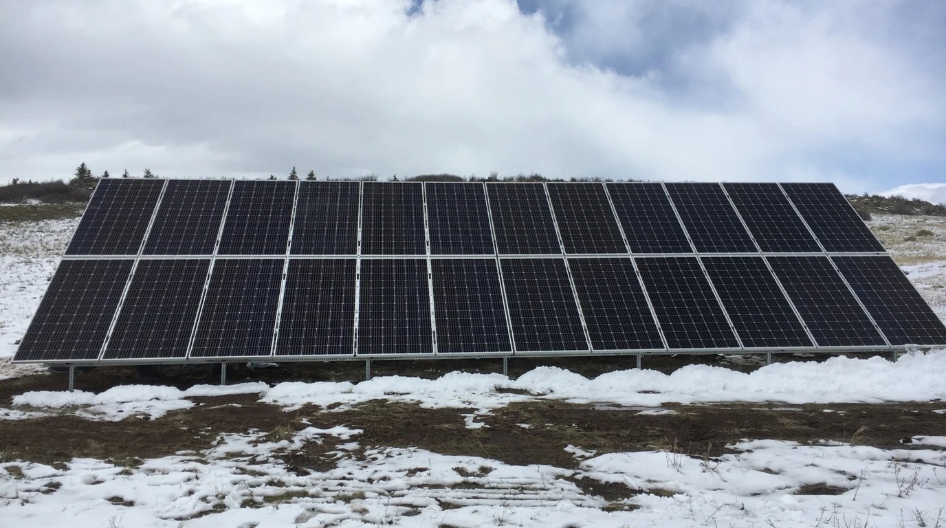
When building a ground-mounted solar array, many DIY builders focus heavily on photovoltaic electrical specs—calculating string voltages, inverter efficiencies, and battery discharge rates. Yet in the field, the most common failure mode of residential ground-mounted solar systems is structural, not electrical.
A modest 16-panel solar array (producing approximately 7 kW to 8 kW) forms a continuous rigid surface of 350 to 420 square feet. Tilted at 30 to 45 degrees toward the equator, this structure functions as an enormous sail anchored to open ground. When a 110 to 130 mph severe wind gust strikes, the array experiences thousands of pounds of upward tensile aerodynamic lift and lateral overturning moment. Add a heavy winter blizzard depositing 40 to 60 pounds per square foot (psf) of wet snow, and the structural posts, purlins, and foundations must bear several tons of dead and live load simultaneously.
Underestimating these mechanical loads leads to bent steel support pipes, sheared mounting hardware, or foundations ripped completely out of the soil.
To ensure your DIY ground mount withstands decades of extreme weather, this guide breaks down the structural physics of wind and snow loading, walks through standard ASCE 7-22 design equations, compares Schedule 40 versus Schedule 80 galvanized pipe columns, details diagonal bracing geometry, and provides concrete safety factors for self-builders.
Engineering Verdict: Free-standing ground-mounted solar arrays are subject to higher aerodynamic turbulence than rooftop arrays due to airflow beneath the table. In open rural terrain (ASCE Exposure Category C), wind gusts of 120 mph generate localized peak uplift pressures exceeding 38 psf. Never rely on nominal fence pipe or thin-wall conduit. Standardize on minimum 2.5-inch or 3-inch nominal Schedule 40 or Schedule 80 hot-dip galvanized structural pipe (ASTM A53 Grade B), install North-South and East-West diagonal knee braces to eliminate parallelogram racking sway, and design foundations with a minimum 1.5x to 2.0x safety factor against overturning.
Aerodynamic Forces and Load Distribution on Tilted Solar Tables
Unlike rooftop solar arrays where panels lie parallel to an existing roof plane and benefit from aerodynamic boundary layer shielding, ground-mounted solar arrays are free-standing tilted bluff bodies. Airflow moves freely both above and below the panel plane, creating complex aerodynamic fluid dynamics.
When turbulent wind approaches a tilted ground array, three distinct structural forces act upon the racking assembly:
Direct Downward Wind Pressure (Windward Attack)
When high-velocity wind strikes the front face of the tilted solar array (typically approaching from the south in northern hemisphere installations), air decelerates rapidly against the panel surface. This deceleration converts kinetic energy into positive static pressure, forcing the array downward toward the ground.
This downward force adds directly to the dead weight of the aluminum rails and photovoltaic modules, loading the front and rear vertical columns in compression and applying downward bending stress to horizontal cross-pipes (purlins).
Aerodynamic Uplift and Leeward Vortex Suction
Wind flowing over the top ridge of the tilted array separates from the trailing edge, generating a low-pressure separation bubble (wake zone) on the backside of the array. According to Bernoulli principles and vortex shedding dynamics, this low-pressure zone acts like an airplane wing, creating strong upward tensile suction.
In severe windstorms, this aerodynamic uplift is the single most destructive force on solar ground mounts. Because standard crystalline solar modules weigh only 2.5 to 3.0 pounds per square foot (dead weight), a moderate uplift pressure of 25 to 35 psf completely overwhelms panel gravity. The racking hardware, pipe fittings, and buried foundations are placed in pure tension, attempting to pull vertical piers out of the soil.
Lateral Overturning Moment and Parallelogram Sway
Wind striking the array from the front or back applies lateral horizontal force (). Because the center of pressure is elevated several feet above grade level, this horizontal thrust creates an overturning moment:
This rotational force drives the rear foundation posts downward into the earth while pulling the front foundation posts upward. Concurrently, wind striking the side of an array (East-West crosswinds) induces shear racking stress, trying to collapse rectangular vertical pipe legs into a flattened parallelogram.
Calculating Wind Velocity Pressure Using ASCE 7-22
In the United States, structural wind design for solar mounting systems is governed by ASCE 7-22 (Minimum Design Loads and Associated Criteria for Buildings and Other Structures).
To calculate the design wind pressure acting on a ground-mounted solar table, structural engineers first determine the velocity pressure () at array height:
Variable Definitions and Parameter Selection
- (Basic Design Wind Speed): The 3-second peak wind gust speed in miles per hour (mph) at 33 feet above ground for your specific geographic location, mapped under ASCE 7-22 Risk Category I or II. Most non-coastal inland regions range from 105 mph to 125 mph, while coastal hurricane zones reach 140 to 170 mph.
- (Velocity Pressure Exposure Coefficient): Accounts for height above ground and terrain roughness. For ground mounts under 15 feet in height:
- Exposure Category B (Suburban, wooded areas, rolling terrain with obstructions):
- Exposure Category C (Open fields, agricultural pastures, grasslands with scattered obstructions):
- Exposure Category D (Flat, unobstructed coastal waterways):
- (Topographic Factor): Accounts for wind acceleration over isolated hills, ridges, or escarpments. On flat terrain, . If installing on a crest of a ridge, can increase wind pressure by 20% to 80%.
- (Wind Directionality Factor): For open solar ground mount structures, standard building codes apply .
- (Ground Elevation Factor): Adjusts for atmospheric air density at high elevations:
- Sea level to 1,000 ft:
- 5,000 ft elevation:
Calculating Design Net Pressure on Solar Panels
Once is established, the total design wind force acting perpendicular to the panel surface is:
Where:
- (Gust Effect Factor): For rigid ground-mounted structures with a natural vibration frequency above 1 Hz, .
- (Net Aerodynamic Pressure Coefficient): Derived from wind tunnel testing on free-standing tilted open tables. Values vary depending on tilt angle () and wind direction:
- Downward maximum pressure coefficient:
- Uplift maximum suction coefficient:
Real-World Wind Calculation Example
Consider a 16-panel array (380 sq ft) in an open rural field (Exposure C) in the Midwest with a 115 mph design gust speed:
- Velocity pressure calculation:
- Peak uplift design pressure:
- Total net upward aerodynamic lift on the array:
The solar modules and racking weight only approximately 1,140 lbs (). Therefore, the foundation piers and pipe clamps must resist over 11,480 pounds of net upward tension attempting to rip the structure out of the soil.
Snow Load Engineering and Shedding Dynamics
In cold northern climates, winter snow accumulation presents a massive static gravity load. Snow weight varies dramatically depending on moisture content:
- Fresh, dry powder: 5 to 8 lbs per cubic foot (pcf)
- Settled, wind-packed snow: 15 to 25 pcf
- Wet, water-saturated snow or freezing rain: 30 to 50 pcf
Under ASCE 7-22, ground snow loads () across North America range from 20 psf in moderate valleys to over 70 to 100 psf in mountain and Great Lakes snowbelts.
Sloped Roof Snow Load Equation
To determine the actual snow pressure () that rests on a tilted solar array, structural engineers apply the sloped surface equation:
Where:
- (Roof Slope Factor): Accounts for natural sliding. Glass-surfaced solar modules are classified as “unobstructed slippery surfaces”.
- For tilt angles below 15 degrees: (Zero shedding)
- For tilt angles between 15 and 70 degrees:
- For tilt angles above 70 degrees: (Complete shedding)
- (Thermal Factor): Because solar cells heat up during daylight (absorbing infrared radiation and generating waste heat), snow touching dark silicon melts quickly, creating a microscopic water lubricant layer that promotes shedding. For unheated open solar arrays, .
The 35-Degree Shedding Threshold
Extensive field research and solar testing benches demonstrate that 35 degrees of tilt is the empirical threshold for reliable snow shedding:
| Tilt Angle | Snow Shedding Behavior | Risk of Snow Damming | Required Structural Design Margin |
|---|---|---|---|
| 10° to 20° | Poor shedding; snow accumulates and compacts throughout winter. | Extreme; heavy ice formation on frame lip. | Full 100% ground snow load () must be engineered. |
| 25° to 30° | Sluggish shedding; requires intense sun and ambient temperatures above -2°C (28°F) to release. | Moderate; snow can remain stuck for days after storms. | 75% to 85% of ground snow load. |
| 35° to 45° | Rapid natural shedding; snow blankets release in clean sheets within hours of daylight. | Low (provided bottom ground clearance is maintained). | 55% to 65% of ground snow load. |
| 50°+ | Immediate shedding; snow slides off continuously during snowfall. | Negligible. | 30% to 40% of ground snow load. |
Critical Requirement: Bottom Drip Clearance
The greatest real-world failure in DIY snow design is insufficient ground clearance at the bottom of the array.
When an array tilted at 40 degrees sheds an 18-inch snowfall, the sliding snow accumulates in a compacted pile directly beneath the lower panel lip. If the bottom edge of the array is only 12 to 18 inches above grade, the shed snow pile quickly contacts the bottom panel frames.
Once snow touches the bottom frame, it forms a mechanical dam. Subsequent snow cannot slide off, building up hundreds of pounds of ice and snow on the bottom edge. This localized cantilever load bends aluminum module frames and shatters tempered glass.
In regions with ground snow loads above 30 psf, always maintain at least 24 to 36 inches of clearance between bare grade level and the lowest edge of the panel frame.
Structural Member Sizing: Pipe Columns and Cross-Rails
The structural backbone of most DIY ground mounts is an engineered truss assembly built from round steel pipe columns and horizontal cross-pipes (often referred to as torque tubes or purlins).
Schedule 40 vs Schedule 80 Galvanized Steel Pipe
Builders must never use residential chain-link fence tubing, lightweight electrical metallic tubing (EMT), or generic exhaust pipe for structural solar supports. Structural ground mounts require ASTM A53 Grade B or ASTM A500 Grade B hot-dip galvanized structural pipe.
The table below compares mechanical section properties for standard nominal pipe sizes (NPS) commonly used in DIY solar racking:
| Nominal Pipe Size (NPS) | Pipe Schedule | Outside Diameter (OD) | Wall Thickness (in) | Weight per Foot (lbs) | Section Modulus () | Moment of Inertia () |
|---|---|---|---|---|---|---|
| 2.0 Inch | Schedule 40 | 2.375 in | 0.154 in | 3.65 lbs | 0.561 | 0.666 |
| 2.0 Inch | Schedule 80 | 2.375 in | 0.218 in | 5.02 lbs | 0.731 | 0.868 |
| 2.5 Inch | Schedule 40 | 2.875 in | 0.203 in | 5.79 lbs | 1.064 | 1.530 |
| 2.5 Inch | Schedule 80 | 2.875 in | 0.276 in | 7.66 lbs | 1.340 | 1.920 |
| 3.0 Inch | Schedule 40 | 3.500 in | 0.216 in | 7.58 lbs | 1.724 | 3.017 |
| 3.0 Inch | Schedule 80 | 3.500 in | 0.300 in | 10.25 lbs | 2.225 | 3.894 |
Column Bending Stress Equation
When lateral wind force strikes the array, vertical pipe posts experience cantilever bending stress. The maximum bending moment occurs at the ground line:
The actual bending stress in the pipe column must not exceed the allowable yield stress of the steel:
Where:
- is the elastic section modulus of the pipe from the engineering table above.
- is the minimum yield strength of ASTM A53 Grade B steel (35,000 psi).
- is the safety factor for allowable stress design (ASD), typically 1.67.
Pipe Sizing Selection Guidelines
- Use 2.0-Inch Schedule 40: Only for small, low-profile arrays (1 to 2 modules high in portrait) in mild wind zones (under 100 mph) and low snow areas (under 20 psf), with post spacing not exceeding 6 feet.
- Use 2.5-Inch Schedule 40: The standard residential benchmark for two-in-portrait or four-in-landscape tables up to 115 mph wind zones and 35 psf snow, with post spans of 7 to 9 feet.
- Use 3.0-Inch Schedule 40 / 80: Required for taller rear posts (over 8 feet tall), open pastures (Exposure C) with 120 to 140 mph wind gusts, heavy snow zones (over 50 psf), or when stretching post spacing to 10 to 12 feet.
The Necessity of Diagonal Cross-Bracing
A rectangular post-and-beam frame without diagonal bracing is fundamentally unstable. Under horizontal wind gusts, the mechanical joints connecting horizontal pipes to vertical posts experience immense rotational torque, leading to parallelogram racking collapse.
To ensure rigid structural performance, every DIY ground mount requires two types of diagonal bracing:
North-South Diagonal Strut (Tilt Stabilizer)
A structural pipe or heavy angle-iron strut must connect the front (southern) post to the rear (northern) post or to the inclined rafter pipe.
This creates a rigid structural triangle. Triangles cannot deform without physically elongating or buckling one of the triangle members. The North-South strut converts overturning wind moments into pure axial tension and compression in the steel posts, virtually eliminating bending fatigue at pipe joints.
East-West Cross-Bracing (Sway Eliminator)
When wind blows across the face of an array from East to West, vertical posts experience lateral shear. For arrays consisting of two or more bays (three or more vertical posts), install diagonal X-bracing between at least one set of adjacent posts.
X-bracing can be constructed from:
- Galvanized Steel Pipe / Angle Iron: Rigidly bolted between adjacent legs.
- High-Tensile Aircraft Cable (3/8” Galvanized Steel): Equipped with heavy-duty drop-forged turnbuckles to pre-tension the array diagonally. Cable X-bracing is lightweight, cost-effective, and exceptionally strong in tension.
Hardware Grading, Fasteners, and Torque Calibration
Even the heaviest Schedule 80 steel pipe will fail if connected with inferior bolts or improperly torqued clamps.
Hardware Material Selection: Grade 8.8 vs Stainless Steel
Solar ground mounts require two distinct categories of fasteners:
- Structural Pipe-to-Pipe Fittings (Hollaender / Kee Klamp / IronRidge Cam-Locks):
- Use high-strength Grade 5 or Grade 8.8 hot-dip galvanized or zinc-flaked structural steel bolts.
- These fasteners provide high shear strength and proof load resistance required to clamp round structural pipes without slipping under multi-ton wind gusts.
- Solar Module Clamps (Mid-Clamps and End-Clamps on Aluminum Rails):
- Use 304 (A2-70) or 316 (A4-70) Marine-Grade Stainless Steel.
- Stainless steel prevents galvanic corrosion when in direct contact with anodized aluminum module frames.
Galling Prevention on Stainless Hardware
A common trap for DIY builders is thread galling (cold welding) on stainless steel fasteners. Because stainless steel alloys form a protective oxide film, tightening bolts with high-speed cordless impact drivers creates intense localized friction heat. The threads bind and seize permanently before reaching full clamping torque.
To eliminate galling:
- Never use an impact wrench on stainless steel solar clamps; always use manual hand ratchets or torque wrenches.
- Apply nickel-based or copper-based anti-seize lubricant to all stainless bolt threads prior to assembly.
Recommended Fastener Torque Specifications
| Fastener Type | Size & Thread Pitch | Material Grade | Recommended Torque (ft-lbs) | Application |
|---|---|---|---|---|
| Module Mid/End Clamps | 1/4”-20 or 5/16”-18 | 304 Stainless Steel | 9 to 12 ft-lbs | Secures solar panel frame to aluminum rail. |
| Rail-to-Pipe U-Bolts | 3/8”-16 | 304 Stainless Steel | 14 to 17 ft-lbs | Clamps aluminum rail to horizontal steel pipe. |
| Pipe Sleeve / Set Screws | 1/2”-13 Square Head | Case-Hardened Steel | 35 to 40 ft-lbs | Locks slip-on structural fittings to pipe column. |
| Structural Frame Bolts | 1/2”-13 Through-Bolt | Grade 8.8 Galvanized | 50 to 55 ft-lbs | Secures North-South diagonal knee braces. |
| Ground Screw Pier Bolts | 5/8”-11 or M16 | Grade 8.8 Galvanized | 85 to 95 ft-lbs | Locks structural pipe base into ground screw collar. |
DIY Safety Factors and Engineering Best Practices
When designing your own ground mount, always incorporate an intentional Factor of Safety (FoS) above baseline calculations.
Licensed civil and structural engineers work with precisely calibrated soil bore logs, certified laboratory material properties, and tight construction tolerances. DIY builders working in open pastures face unknown soil conditions, variable rock layers, and hand-tightened fittings.
Recommended Safety Margins
- Foundation Uplift and Overturning: Apply a minimum 1.5x to 2.0x safety factor. If wind analysis dictates 1,500 lbs of uplift per post, size your ground screws or concrete piers to resist at least 2,500 to 3,000 lbs of pull-out tension.
- Pipe Column Section Modulus: If your calculations indicate 2.0-inch Schedule 40 pipe is stressed to 85% of its yield limit under 115 mph winds, upgrade to 2.5-inch or 3.0-inch pipe. The incremental cost of heavier steel pipe is minuscule compared to replacing a collapsed 8 kW solar array.
- Snow Accumulation Safety: In mountain regions, design for the 50-year historical maximum snow depth rather than average seasonal totals.
Final Construction Inspection Checklist
Before mounting solar panels onto your completed ground rack, verify the following six critical structural milestones:
- Plumb and Level Verification: Ensure all vertical pipe columns are plumb within 0.5 degrees using a magnetic torpedo level.
- Torque Audit: Systematically check every bolt, set screw, and clamp with a calibrated torque wrench, marking verified bolt heads with a paint pen.
- Diagonal Bracing Tension: Confirm all North-South knee braces and East-West X-cables are rigid with zero slack or mechanical play.
- Ground Clearance Check: Measure distance from grade to the lowest panel rail edge; confirm at least 24 to 36 inches in snow country.
- Set Screw Bite: Verify that cup-point set screws on slip-on pipe fittings have visibly indented the galvanized pipe wall to prevent axial slipping under vibration.
- Grounding and Bonding: Ensure all aluminum rails, copper bonding jumpers, and steel pipe columns are bonded to a ground rod per NEC 250 and 690 requirements.