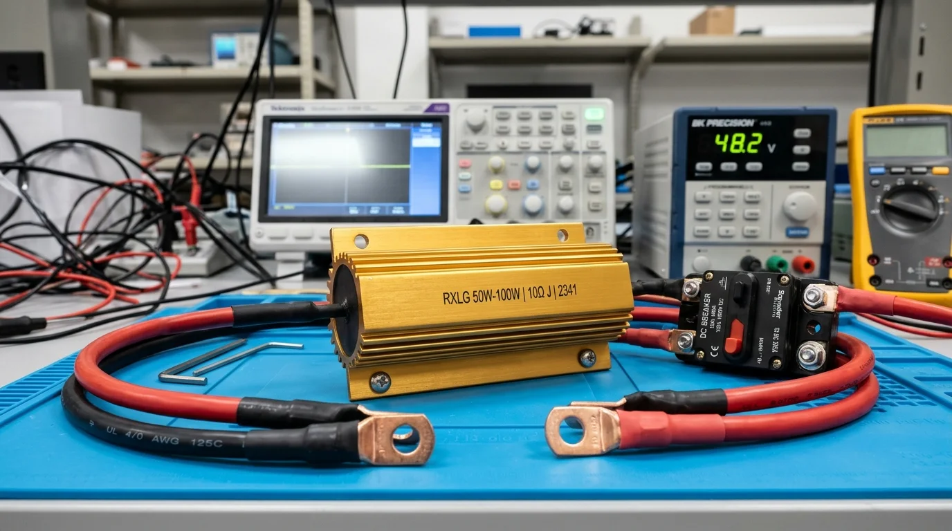
Every solar builder remembers the shock of their first inverter connection: you strip the heavy 4/0 AWG battery cable, bring the terminal lug toward the inverter DC post, and—BANG! A blinding flash and a loud gunshot-like pop occur, sending a shower of molten copper sparks across your workbench and leaving black carbon pitting on brand-new hardware.
Many DIYers assume they made a disastrous wiring mistake or shorted positive to negative.
In reality, the circuit was wired correctly. You experienced capacitive inrush current.
High-capacity off-grid inverters—including models like the Victron MultiPlus-II, EG4 6000XP, and Growatt SPF 5000ES—house massive banks of internal electrolytic capacitors on their DC input bus. When empty, these capacitors act as an instantaneous dead short circuit.
In this technical guide, we explain the physics of uncharged capacitors, detail the severe damage caused by inrush arcing, demonstrate the mathematical formulas to size a pre-charge resistor, and show you how to build a simple, foolproof pre-charge circuit.
Never close a main DC disconnect breaker onto an uncharged inverter. An uncharged capacitor bank pulls over 1,000 Amperes of instantaneous inrush current from low-impedance lithium batteries, permanently welding breaker contacts and tripping sensitive BMS short-circuit protection. Placing a 30-ohm to 50-ohm 50W wirewound resistor across the breaker for 3 to 5 seconds pre-charges the capacitors gently, reducing inrush current below 2 Amperes with zero sparks.
Check Pre-Charge Resistors on Amazon →
The Physics of Inverter Input Capacitors at Initial Connection
To convert direct current (DC) into smooth 60Hz pure sine wave alternating current (AC), high-power inverters switch their internal MOSFET or IGBT transistors on and off tens of thousands of times per second (PWM switching).
This rapid pulsing generates extreme high-frequency ripple currents on the DC input bus. To buffer these current spikes and maintain steady voltage, inverters place a large bank of heavy-duty electrolytic capacitors across the positive and negative DC input terminals ().
The Uncharged Capacitor as a Dead Short
The voltage across a capacitor cannot change instantaneously (). At the precise microsecond electrical contact is made (), the only resistance limiting current flow is the minuscule internal resistance (ESR) of the capacitors () and the battery cable resistance ().
- Equivalent loop resistance is less than 0.04 ohms
- In a 51.2V system, peak current exceeds 1,200 Amperes
- Reaches peak amperage in under 50 microseconds
Controlled Current Ramping
When a 30-ohm resistor is inserted into the circuit before closing the main breaker, Ohm’s law strictly limits the maximum possible current to: The capacitors charge smoothly over several tenths of a second with zero sparking and zero component stress.
- Eliminates 99.8% of inrush current spike
- Protects breaker contacts from contact pitting
- BMS solid-state switches remain completely calm
Why Direct Inrush Arcing Destroys Your Equipment
When a 1,000+ Ampere inrush arc discharges across open electrical contacts, the damage is both immediate and cumulative:
+-----------------------------------------------------------------------------------------+
|                  HARDWARE DAMAGE MODES FROM UNCONTROLLED CAPACITOR INRUSH               |
+-----------------------------------------------------------------------------------------+
| Component Affected    | Failure Mechanism                        | Real-World Symptom   |
+-----------------------+------------------------------------------+----------------------+
| DC Circuit Breakers   | 4,000°F plasma arc vaporizes silver plating| Pitted contacts,     |
| (100A–250A)           | and welds moving mechanical contacts shut| breaker fails to trip|
+-----------------------+------------------------------------------+----------------------+
| Smart BMS             | Inrush triggers Short Circuit Protection | Inverter refuses to  |
| (Solid-State MOSFETs) | (SCP); inductive flyback spikes exceed   | turn on; blown BMS   |
|                       | MOSFET drain-source voltage threshold    | internal switchgate  |
+-----------------------+------------------------------------------+----------------------+
| Inverter Input Caps   | Internal aluminum foil tabs experience   | Shortened capacitor  |
| (Electrolytic Banks)  | severe electrodynamic mechanical stress  | lifespan; ESR rise   |
+-----------------------+------------------------------------------+----------------------+
| High-Current Plugs    | Metal vaporizes at plug tip, depositing  | Blackened plugs; high|
| (Anderson / Radsok)   | non-conductive carbon slag               | contact resistance   |
+-----------------------------------------------------------------------------------------+
The Contact Welding Hazard
The most dangerous consequence of uncontrolled inrush current is contact welding inside DC circuit breakers. During the microsecond before the mechanical breaker contacts clamp together, an intense plasma arc bridges the microscopic air gap. The localized heat liquefies the copper/silver contact faces.
When the contacts meet, the liquid metal fuses solid. If an electrical short later occurs while operating, the breaker may fail to release, keeping a live fault connected to your battery bank.
Resistor Sizing Math: Calculating the RC Time Constant
Selecting a pre-charge resistor requires balancing two engineering constraints:
- Resistance (): High enough to limit peak current to safe levels (< 2A to 3A), but low enough to charge the capacitors quickly (< 2 seconds).
- Power Rating (Watts): High enough to absorb the total capacitive energy pulse without burning out the resistive wire.
The RC Time Constant Formula
The charging curve of an RC circuit is governed by the time constant (tau):
Where:
- = Resistance in Ohms ()
- = Inverter input capacitance in Farads ()
- = Time in seconds required to charge the capacitors to 63.2% of full battery voltage.
Because capacitor charging is asymptotic:
- After : Capacitors reach 95.0% of battery voltage.
- After : Capacitors reach 99.3% of battery voltage (effectively fully charged).
Step-by-Step Engineering Example
Let’s calculate the ideal pre-charge resistor for a 48V 6,000W Inverter with a () internal capacitor bank running on a 52.0V battery pack:
Resistance Selection ()
Calculate the time constant:
To reach 99.3% voltage ():
In just three-quarters of a second, the inverter capacitor bank charges to over 51.5V!
Peak Current Calculation
Energy Dissipated in the Resistor
The total electrical energy () stored in the capacitor bank (and identically dissipated as heat in the resistor) is:
Because 6.76 Joules is dissipated over 0.75 seconds, the average power during the pulse is roughly 9 Watts. However, the instantaneous peak power at is:
A standard tiny 1/4-watt carbon film resistor would instantly vaporize. However, a 50-watt or 100-watt aluminum-clad wirewound resistor possesses sufficient thermal mass in its ceramic core and aluminum casing to absorb this pulse with virtually zero temperature rise.
Practical Pre-Charge Circuits: Three Wiring Topologies
Here are the three most reliable methods used by professional off-grid solar engineers:
1
The Handheld Resistor Wand (Simplest / Portable)
Solder insulated test leads to a 50-ohm 50W aluminum resistor. Terminate one end with an alligator clip and the other with an insulated probe. Clip across the main breaker terminals for 5 seconds before closing the breaker.
2
Parallel Push-Button Bypass (Most Popular for Homesteads)
Wire a momentary normally-open (NO) heavy-duty push button in series with a 30-ohm 50W resistor directly across the line and load terminals of your main DC disconnect breaker. Press button for 5 seconds, then flip breaker ON.
3
Automatic Time-Delay Relay & Contactor (Commercial Automated)
A small 12V/48V timer relay energizes a pre-charge pilot relay. After a 2-second delay, the timer triggers a massive 400A main EV contactor, simultaneously disconnecting the pre-charge branch.
Step-by-Step Commissioning Procedure Using a Push-Button
If you install a permanent push-button pre-charge circuit on your solar power wall, follow this exact four-step commissioning checklist:
Verification of Open Circuit
- Ensure the main DC breaker between the battery bank and inverter is switched OFF.
- Switch off all AC loads and turn the inverter power switch to OFF.
Pre-Charge Activation
- Press and firmly hold down the momentary pre-charge push-button.
- Keep the button depressed for 3 to 5 continuous seconds.
- If you have a voltmeter placed across the inverter DC input lugs, you will watch the voltage smoothly climb from 0V up to within 1V of your battery voltage.
Main Breaker Engagement
- While still holding down the pre-charge button, flip the main DC circuit breaker to the ON position.
- Because the voltage across the breaker contacts is now virtually identical (51.8V on line vs 51.5V on load), the contacts close with zero arc and zero spark.
Release and Operation
- Release the momentary push-button.
- Switch on your inverter’s master power button. The unit boots cleanly without stressing BMS protection MOSFETs.
Recommended Hardware Specifications
To ensure long-term fire safety, select industrial wirewound components rated for continuous pulse duty:
| Parameter / Component | 12V / 24V Systems | 48V Systems (Homestead Standard) | High-Voltage Commercial (100V+) |
|---|---|---|---|
| Resistor Resistance () | 10 to 20 | 30 to 50 | 100 to 200 |
| Resistor Power Rating | 25 Watts – 50 Watts | 50 Watts – 100 Watts | 100 Watts – 200 Watts |
| Resistor Construction | Gold Aluminum-Clad Wirewound | Gold Aluminum-Clad Wirewound | Vitreous Enamel Tubular |
| Push-Button Rating | 12V/24V 5A Momentary (NO) | 125V DC rated Momentary (NO) | Industrial Panel Push-Button |
| Hookup Wire Gauge | 16 AWG or 14 AWG Silicone | 14 AWG or 12 AWG High-Temp | 12 AWG High-Temp Shielded |
50W 30-Ohm / 50-Ohm Aluminum Clad Wirewound Resistor
Heavy-duty extruded aluminum heatsink body, gold anodized, rated for high-current pulse absorption.
View Pre-Charge Resistors on Amazon →