Building a productive, fully autonomous off-grid homestead or timber workshop is a dream for many woodworkers, carpenters, and off-grid builders. Heavy cast-iron woodworking machinery—such as 10-inch cabinet table saws, 20-inch thickness planers, 8-inch jointers, and wide-belt sanders—forms the core of timber framing and fine furniture production.
However, operating a woodshop introduces an electrical demand that differs fundamentally from general residential power usage: the central dust collection system.
Unlike a table saw or miter saw, which cuts intermittently for three to twenty seconds at a time, a central cyclone dust collector (typically powered by a 3HP to 5HP continuous-duty induction motor) must run continuously throughout milling operations.
When you start a 5HP dust collector while your thickness planer is already feeding heavy rough-sawn hardwood, the instantaneous combined electrical draw can exceed the capabilities of standard off-grid solar inverters, tripping breakers, sagging battery bus voltages, and causing workshop lights to brown out.
This engineering guide examines the real-world power dynamics of running heavy cyclone dust collection on off-grid solar. We calculate starting inrush surges, analyze continuous dual-motor load demands, evaluate Variable Frequency Drive (VFD) soft-start retrofits, and detail static electricity grounding to safeguard nearby lithium battery storage.
Executive Summary: The Heavy Shop Load Reality
Can you run a professional woodshop with a 5HP cyclone dust collector on off-grid solar? Yes, but it requires an engineered power plant:
+-----------------------------------------------------------------------------------+
|               OFF-GRID WOODSHOP POWER REQUIREMENTS AT A GLANCE                    |
+-----------------------------------------------------------------------------------+
|  1. Motor Inrush Challenge: A 5HP single-phase TEFC induction motor demands       |
|     between 90A and 125A of instantaneous Locked Rotor Amps (LRA) at 240V AC.     |
|                                                                                   |
|  2. Continuous Concurrent Draw: Running a 5HP cyclone (5.2kW) alongside a 3HP     |
|     table saw (3.3kW) requires 8.5kW continuous AC output without thermal drift.  |
|                                                                                   |
|  3. Battery Bank Discharge Muscle: An 8.5kW AC load demands 185 to 200 Amperes    |
|     continuous DC current from a 48V LiFePO4 bank, requiring low-impedance packs. |
|                                                                                   |
|  4. Mitigation Breakthrough: Converting the blower to a 3-phase motor driven by a  |
|     digital VFD slashes starting surge to 1.0x running current with zero inrush.  |
+-----------------------------------------------------------------------------------+
Without soft-starting technology, a standard 8kW to 12kW split-phase hybrid solar inverter (such as an EG4 12000XP or Deye 8kW) cannot start a 5HP single-phase cyclone motor without throwing overcurrent faults.
Motor Thermodynamics: Running Amps vs Starting Inrush (LRA)
To size an inverter accurately, we must differentiate between continuous running power and instantaneous starting transients.
Full Load Amps (FLA) of Single-Phase Induction Motors
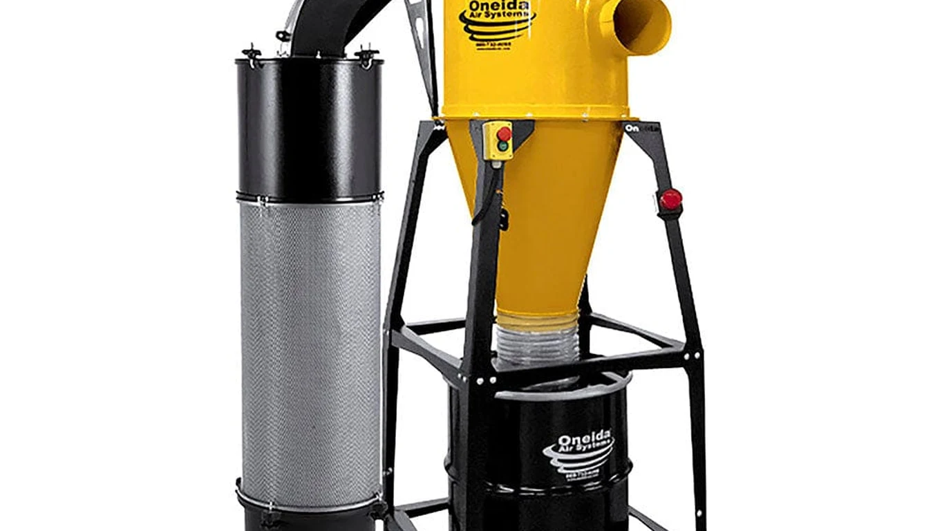
Industrial dust collectors (such as the Oneida Super Dust Gorilla, Laguna C|Flux:3, or Grizzly G0441) utilize Totally Enclosed Fan-Cooled (TEFC) induction motors:
- 3HP Single-Phase 240V Motor: Typical Full Load Amperage () ranges from 14.0 to 16.5 Amps. Running power draw equals:
- 5HP Single-Phase 240V Motor: Typical ranges from 21.0 to 24.5 Amps. Running power draw equals:
Accounting for blower impeller aerodynamic resistance and backpressure in long ductwork, a 5HP cyclone motor operates under continuous electrical loads between 4,800 and 5,300 Watts.
The Locked Rotor Amperage Shockwave
When voltage is first applied to a stationary induction motor, the rotor is not spinning. There is zero counter-electromotive force (back-EMF) to oppose current flow. The motor presents only the raw DC resistance and leakage inductance of its copper stator windings:
For a standard NEMA Code G or Code H 5HP motor:
- Full Load Amps (): 22 Amperes
- Locked Rotor Amps (): at 240V
- Peak Instantaneous Apparent Power:
+-----------------------------------------------------------------------------------+
|               ACROSS-THE-LINE MOTOR STARTING INRUSH COMPARISON                    |
+-----------------------------------------------------------------------------------+
| Motor Rating   | Running Amps (FLA) | Starting Surge (LRA) | Instantaneous Surge  |
+----------------+--------------------+----------------------+----------------------+
| 2HP Induction  | 10.5 Amps at 240V  | 55 to 65 Amps        | 13,200 to 15,600 VA  |
| 3HP Induction  | 15.0 Amps at 240V  | 80 to 95 Amps        | 19,200 to 22,800 VA  |
| 5HP Induction  | 22.0 Amps at 240V  | 110 to 135 Amps      | 26,400 to 32,400 VA  |
+----------------+--------------------+----------------------+----------------------+
A 29kVA surge lasting 300 to 600 milliseconds will immediately trip the fast-acting silicon protection circuits of most 8kW to 12kW transformerless solar inverters.
Concurrent Load Modeling: The Dual-Motor Shop Reality
In real woodworking operations, the dust collector never runs in isolation. It operates concurrently with the primary cutting tool.
Worst-Case Load Scenarios: 5HP Cyclone + 3HP Table Saw
Consider a typical shop operation: milling heavy white oak timbers on a 3HP cabinet table saw while the 5HP cyclone dust collector evacuates chips:
- Continuous Running Demand:
- 5HP Cyclone Blower: 4,850 Watts
- 3HP Cabinet Saw (Hardwood Ripping): 2,950 Watts
- Overhead LED High-Bay Lighting: 300 Watts
- Workshop Exhaust Fan: 200 Watts
- Total Continuous Running Load: 8,300 Watts (34.6A at 240V)
- The Dynamic Inrush Scenario:
- The 5HP dust collector is running steadily (consuming 4,850W).
- The woodworker steps up to the table saw and engages the magnetic start switch.
- The stationary 3HP saw motor draws its starting surge ().
- Total Momentary Peak Demand: !
+-----------------------------------------------------------------------------------+
|                 CONCURRENT WORKSHOP LOAD POWER CASCADE                            |
+-----------------------------------------------------------------------------------+
|  Continuous Steady-State Operation:                                               |
|  • 5HP Cyclone Dust Collector                  = 4,850 Watts                      |
|  • 3HP Cabinet Table Saw (under feed load)     = 2,950 Watts                      |
|  • Shop Lighting & Electronics                 =   500 Watts                      |
|  Total Continuous AC Output Demand             = 8,300 Watts                      |
|                                                                                   |
|  Transient Motor Strike (Starting Saw while Cyclone Runs):                       |
|  • Cyclone Running Power                       = 4,850 Watts                      |
|  • Table Saw Inrush Surge (LRA for 400ms)      = 20,400 Watts                     |
|  Total Momentary System Demand                 = 25,250 Watts                     |
+-----------------------------------------------------------------------------------+
If your solar power plant consists of a single 8kW inverter, this simultaneous motor event will collapse the AC bus voltage, rebooting computers and throwing inverter overload errors.
Variable Frequency Drives: The Zero-Inrush Soft-Start Solution
The definitive engineering solution to running a heavy cyclone dust collector on off-grid solar is converting the motor to a three-phase Variable Frequency Drive (VFD) system.

Replacing Single-Phase with Three-Phase 240V Motors
While single-phase motors rely on centrifugal switches and start capacitors that demand brutal inrush spikes, three-phase AC induction motors can be continuously modulated across both frequency and voltage:
- Sourcing the Motor: Modern 3HP and 5HP 3-phase 240V/480V TEFC C-face motors (such as Leeson, Baldor, or WEG) are readily available, highly efficient, and possess no mechanical start switches to wear out.
- Single-Phase to Three-Phase Inversion: A digital VFD (such as an AutomationDirect GS20 or Lapond 5HP VFD) accepts standard single-phase 240V AC power from the solar inverter, converts it to an internal 340V DC bus, and then synthesizes a clean, variable-frequency 3-phase AC output.
Programmable Ramp-Up Acceleration: Zero Inrush Current
In a VFD-controlled blower setup:
- When the operator hits the remote dust collector button, the VFD does not slam full 60Hz voltage into the motor.
- Instead, the VFD starts at 1 Hz and gently ramps up to 60 Hz over 8 to 12 seconds.
- Stator current never exceeds 100% to 110% of Full Load Amps () throughout the entire starting sequence.
- The 29kVA starting inrush surge is completely eliminated! The solar inverter sees only a smooth, progressive ramp from 200W up to 4,800W over ten seconds.
+-----------------------------------------------------------------------------------+
|               ACROSS-THE-LINE START VS VFD SOFT-START PROFILE                     |
+-----------------------------------------------------------------------------------+
| Current                                                                           |
|   ^                                                                               |
|   |   +------+ (125A LRA Across-the-Line Spike - Trips Inverters!)                |
|   |   |      |                                                                    |
|   |   |      +---------------------+ (22A Running FLA)                            |
|   |   |                            |                                              |
|   |   |  VFD Soft-Start Ramp       |                                              |
|   |   |       /--------------------+ (Smooth 10-Second Ramp to 22A Max)           |
|   |   |      /                                                                    |
|   |   |     /                                                                     |
|   0---+----+------------------------------------> Time (Seconds)                  |
|       0s   1s                      10s                                            |
+-----------------------------------------------------------------------------------+
Fan Affinity Laws: Sashing Power Consumption with VFD Speed Control
Beyond eliminating starting surges, equipping a dust collector with a VFD unlocks massive electrical energy savings through the Fan Affinity Laws.
The Cubic Power Relationship of Centrifugal Blowers
In centrifugal fan and blower physics, volumetric airflow () is directly proportional to impeller rotational speed (), but shaft power consumption varies with the cube of rotational speed:
Where represents the electrical supply frequency in Hertz.
Calculating the 48Hz Sweet Spot for Off-Grid Savings
When collecting dust from a router table, drill press, or small bandsaw, the shop does not require the maximum 1,800 CFM of a 5HP blower running at full 60Hz:
- Operating at Full Speed (60Hz): Power Draw = 5,000 Watts (100% Flow, 1,800 CFM).
- Throttling to 80% Speed (48Hz):
+-----------------------------------------------------------------------------------+
|                 FAN AFFINITY SPEED VS POWER CONSUMPTION BENCHMARK                 |
+-----------------------------------------------------------------------------------+
| VFD Frequency  | Impeller Speed | Airflow (CFM) | Power Draw   | Energy Savings   |
+----------------+----------------+---------------+--------------+------------------+
| 60 Hz (Max)    | 3,450 RPM      | 1,800 CFM     | 5,000 Watts  | Baseline (0%)    |
| 54 Hz (90%)    | 3,105 RPM      | 1,620 CFM     | 3,645 Watts  | 27% Power Cut    |
| 48 Hz (80%)    | 2,760 RPM      | 1,440 CFM     | 2,560 Watts  | 49% Power Cut!   |
| 42 Hz (70%)    | 2,415 RPM      | 1,260 CFM     | 1,715 Watts  | 66% Power Cut!   |
+----------------+----------------+---------------+--------------+------------------+
By programming a dual-speed selector switch on the VFD, an off-grid woodworker can run everyday sanding and sawing at 48Hz, saving nearly 2,500 Watts of continuous battery drain, switching to 60Hz only during high-volume planer and jointer runs.
Battery Bank C-Rate and DC Busbar Sizing for Continuous Milling
Operating an 8,300W continuous workshop load places heavy demands on the 48V DC battery bank.
DC Discharge Amperage and Battery C-Rate
To deliver 8,300 Watts of AC power through a modern hybrid inverter operating at 92% conversion efficiency:
At a nominal battery discharge voltage of 51.2V DC (standard 16S LiFePO4 resting plateau):
- Single 100Ah Battery Pack: A single 100Ah server rack battery is typically rated for 100A continuous discharge (1.0C rate). Attempting to draw 176A from a single battery will trigger immediate BMS overcurrent protection or cause severe thermal degradation.
- Three-Pack Parallel Array (300Ah / 15kWh): Paralleling three 100Ah battery modules divides the 176A load down to 58.6A per pack (0.58C rate), maintaining cell temperatures within comfortable limits and minimizing internal resistance voltage sag.
+-----------------------------------------------------------------------------------+
|               BATTERY BANK CONFIGURATION UNDER 8.3kW SHOP LOAD                    |
+-----------------------------------------------------------------------------------+
| Battery Array Size | Total Capacity | Pack Discharge Rate | Voltage Sag at Bus    |
+--------------------+----------------+---------------------+-----------------------+
| 1x 100Ah (5.1kWh)  | 100 Ah (48V)   | 1.76C (OVERLOAD)    | Trips BMS Disconnect  |
| 2x 100Ah (10.2kWh) | 200 Ah (48V)   | 0.88C (High Stress) | Drops 1.8V to 2.2V    |
| 3x 100Ah (15.3kWh) | 300 Ah (48V)   | 0.58C (Optimal)     | Drops < 0.6V (Stable) |
| 4x 100Ah (20.4kWh) | 400 Ah (48V)   | 0.44C (Cool / Safe) | Drops < 0.3V (Ideal)  |
+--------------------+----------------+---------------------+-----------------------+
DC Cable Gauge and Main Overcurrent Protection
At 176A continuous DC current, heavy conductors are mandatory to eliminate fire hazards:
- Conductor Sizing: Main battery cables between the central busbar and inverter must be minimum 4/0 AWG (0000) pure copper welding cable rated for 90°C.
- Overcurrent Protection: The main positive busbar feed must be protected by a 250A to 300A Class T fuse possessing an Interrupting Rating () of at least 20,000 Amperes to handle dead-short lithium fault currents.
Electrostatic Discharge Mitigation: Grounding Plastic PVC Ducting
A critical safety issue unique to woodworking dust collection is triboelectric electrostatic charge generation.
The Static Spark Hazard in Wood Dust Systems
When millions of dry wood shavings and fine sawdust particles travel through non-conductive PVC or ABS ducting at 4,000 feet per minute, electron transfer generates static potentials exceeding 20,000 to 50,000 Volts:
- The Dust Explosion Myth vs Real Shock Hazards: While catastrophic deflagration of wood dust requires specific concentrations and small micron sizes rarely found in amateur ducting, a 30,000-Volt electrostatic discharge (ESD) will deliver severe, painful shocks to the operator.
- Threat to Solar Electronics: If the workshop shares a wall with the power room, an ungrounded static discharge jumping from a PVC blast gate to a metal building frame or electrical conduit will send an electromagnetic pulse (EMP) through nearby sensor wires, corrupting CAN-bus/RS485 communications between the inverter and battery BMS.
Proper Spiral Duct Grounding Protocol
To eliminate static buildup safely:
+-----------------------------------------------------------------------------------+
|               PROPER DUCTWORK STATIC GROUNDING ARCHITECTURE                       |
+-----------------------------------------------------------------------------------+
|  [ Cyclone Metal Housing ] <==== #10 Bare Copper Wire ===== [ Shop Ground Bar ]   |
|            |                                                                      |
|            +--- Continuous Bare Copper Wire Wrapped Spirally Around PVC Duct      |
|            |    (Pitch: 1 Turn every 6 to 8 Inches along all trunk lines)         |
|            |                                                                      |
|            +--- Sheet Metal Screws Inserted into Duct Interior every 3 Feet       |
|                 (Collects Static Charges from Moving Internal Dust Cloud)         |
|                                                                                   |
|            +--- Wire Bridge Across All Flexible Hoses & Blast Gates               |
+-----------------------------------------------------------------------------------+- Spiral Wire Wrap: Wrap a bare 12 AWG or 10 AWG solid copper wire spirally around the exterior of all PVC pipe runs.
- Internal Contact Screws: At 3-foot intervals, drive a small sheet-metal screw through the pipe wall into the internal airflow path so the moving dust cloud physically touches the grounded screw tip.
- Bond to Main Ground: Connect the drain wire directly to the workshop’s equipment grounding conductor (EGC) busbar. Never leave static wires floating!
Complete Woodshop Solar Sizing Checklist
Before ordering equipment for an off-grid woodworking facility, verify that your electrical infrastructure fulfills this engineering checklist:
+-----------------------------------------------------------------------------------+
|                     OFF-GRID WOODSHOP COMMISSIONING AUDIT                         |
+-----------------------------------------------------------------------------------+
| [X] Inverter Sizing: Minimum 12kW to 15kW split-phase continuous capacity         |
|     (e.g., Sol-Ark 15K, EG4 18kPV, or dual stacked Victron Quattro 48/10000).    |
|                                                                                   |
| [X] Blower Soft-Start: 3-Phase 240V motor with digital VFD programmed with a      |
|     10-second acceleration ramp to eliminate 100A+ motor inrush surges.          |
|                                                                                   |
| [X] Fan Affinity Optimization: Program VFD dual-speed presets (48Hz for small     |
|     tools to save 2.5kW; 60Hz for heavy planers and shapers).                     |
|                                                                                   |
| [X] Battery Bank Scale: Minimum 300Ah at 48V (15.3kWh) LiFePO4 to keep continuous|
|     discharge rates under 0.6C during multi-machine milling runs.                 |
|                                                                                   |
| [X] DC Cabling & Fusing: 4/0 AWG copper welding cables with 250A/300A Class T    |
|     fuse protection between battery busbar and inverter.                          |
|                                                                                   |
| [X] Static Grounding: Grounded copper drain wire installed along all PVC dust     |
|     pipes to dissipate 20kV+ triboelectric charges away from inverter electronics.|
+-----------------------------------------------------------------------------------+
By replacing raw single-phase inrush spikes with smooth VFD acceleration and matching continuous battery discharge rates to concurrent motor loads, woodworkers can run heavy commercial cyclone collection systems entirely on clean solar power without compromise.
