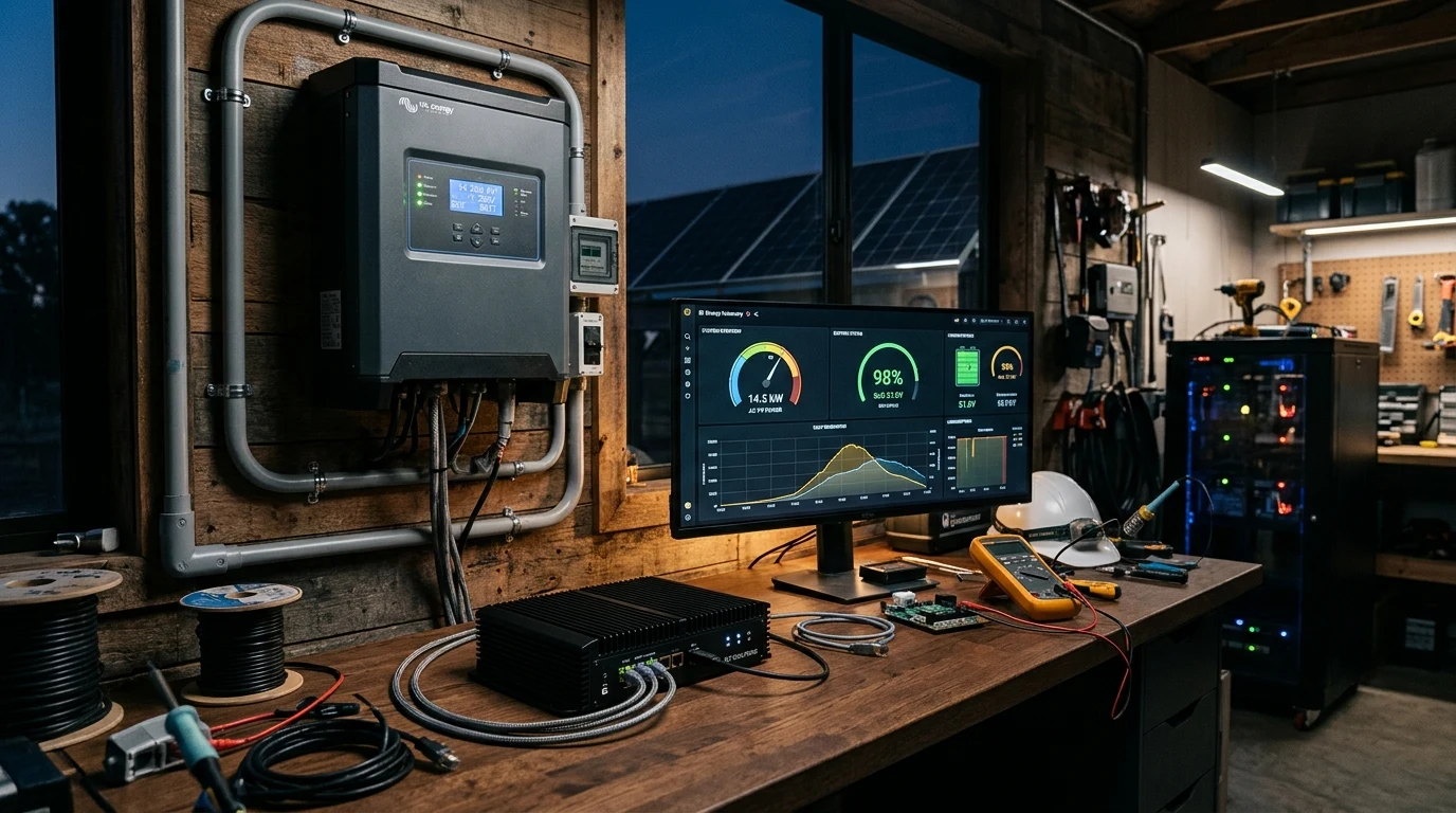
In modern residential and commercial solar installations, monitoring has become synonymous with proprietary mobile apps and vendor-managed cloud portals. Brands such as SolarEdge, Enphase, Growatt, Sol-Ark, Deye, and EG4 encourage installers to connect hardware to Wi-Fi dongles that beam telemetry to remote overseas servers.
For an off-grid homestead, remote cabin, or mission-critical backup installation, cloud-dependent monitoring is an unacceptable engineering vulnerability:
- Internet Fragility: If a winter storm downs satellite broadband or cellular towers, all system visibility vanishes precisely when monitoring battery reserves is most vital.
- Telemetry Latency: Vendor cloud portals update telemetry at intervals ranging from two to fifteen minutes. You cannot perform automated high-speed load shedding or generator control when telemetry is five minutes behind reality.
- Vendor Lock-in and Security: Third-party servers retain the power to push unverified over-the-air (OTA) firmware changes, alter device capabilities, or shutter operations entirely if corporate servers decommission older product lines.
Fortunately, virtually every professional hybrid inverter and charge controller features an industrial-standard hardware port that bypasses the cloud entirely: the RS485 serial communication bus operating the open Modbus protocol.
By tapping directly into the inverter’s local serial port, engineers can extract sub-second telemetry (solar PV voltage, string current, battery state of charge, AC power factor, heat sink temperatures) directly into an on-premises home automation server such as Home Assistant.
This authoritative engineering guide details the physical layer specifications of RS485 differential communication, explains how to avoid destructive ground loops and signal reflections, provides a masterclass in Modbus register decoding, and outlines the automation logic needed to build an autonomous, zero-cloud power management hub.
Executive Summary: The Necessity of Local Offline Telemetry
The operational contrast between vendor cloud portals and local RS485 Modbus polling defines overall off-grid resilience:
+-----------------------------------------------------------------------------------+
|               VENDOR CLOUD PORTAL vs LOCAL MODBUS RTU TELEMETRY                   |
+----------------------+-----------------------------+------------------------------+
| PARAMETER            | Vendor Cloud Portal         | Local RS485 Modbus Polling   |
+----------------------+-----------------------------+------------------------------+
| Data Refresh Rate    | 2 to 15 Minutes             | 500 Milliseconds to 1 Second |
| Internet Dependency  | Mandatory (Down if ISP down)| ZERO (100% Local LAN / RS485)|
| Automation Response  | Sluggish / Unreliable       | Sub-Second Real-Time Control |
| Protocol Standard    | Proprietary Encrypted API   | Open Industrial Modbus RTU   |
| Data Sovereignty     | Stored on Overseas Cloud    | 100% On-Premises InfluxDB/HA |
| Command Capabilities | Often Read-Only or Rate-Ltd | Full Read/Write Register Acc |
| Long-Term Lifespan   | Tied to Corporate Servers   | Indefinite (No End-of-Life)  |
+----------------------+-----------------------------+------------------------------+
When building an autonomous energy system, the monitoring and control loop must reside inside the building envelope. If an auxiliary well pump or electric water heater needs to be shed before an inverter trips on overload, the decision and execution must occur in milliseconds—not minutes.
Physical Layer Engineering: Differential Signaling and Bus Wiring
The foundation of robust local communication begins at the physical layer, governed by the EIA/TIA-485 (RS485) standard.
A typical solar inverter room is a brutally noisy electromagnetic environment. High-power Insulated Gate Bipolar Transistors (IGBTs) and Silicon Carbide (SiC) MOSFETs switch hundreds of volts at frequencies between 16 kHz and 64 kHz, radiating intense electromagnetic interference (EMI).
Standard single-ended serial communication (such as RS232, which measures voltage relative to a shared ground wire) fails catastrophically in solar environments because radiated switching noise easily exceeds signal voltage thresholds.
+-----------------------------------------------------------------------------------+
|               RS485 DIFFERENTIAL VOLTAGE NOISE REJECTION                          |
+-----------------------------------------------------------------------------------+
|                                                                                   |
|  TRANSMITTER DRIVER                                         RECEIVER COMPARATOR   |
|                                                                                   |
|  Line A (D+) ----[ +2.0V Pulse ]---------\ /----------[ +2.0V + V_noise ]-----\   |
|                                           X                                    [+]|
|  Line B (D-) ----[ -2.0V Pulse ]---------/ \----------[ -2.0V + V_noise ]----/[-]|
|                                                                                |  |
|                                  TWISTED PAIR CABLE                            v  |
|                                                                        V_diff = 4V|
|                                                                                   |
|  RESULT: Equal common-mode noise (V_noise) induced on both wires is subtracted!   |
|          V_out = (V_A + V_noise) - (V_B + V_noise) = V_A - V_B                    |
|                                                                                   |
+-----------------------------------------------------------------------------------+
Differential Voltage and Common-Mode Noise Rejection
RS485 overcomes electromagnetic noise by utilizing balanced differential signaling across a twisted pair of conductors, designated as Line A () and Line B ():
- To transmit a logic state of “1” (Mark), the transmitter drives Line A negative relative to Line B ().
- To transmit a logic state of “0” (Space), the transmitter drives Line A positive relative to Line B ().
Because the two conductors are tightly twisted together along the length of the cable, any external electromagnetic noise radiated by the inverter’s switching stage couples into both conductors equally ().
When the receiving transceiver processes the incoming signal, it measures solely the voltage differential between the two lines:
The common-mode noise is completely cancelled out, allowing error-free data transmission at baud rates up to 115,200 baud over cable distances exceeding several hundred meters.
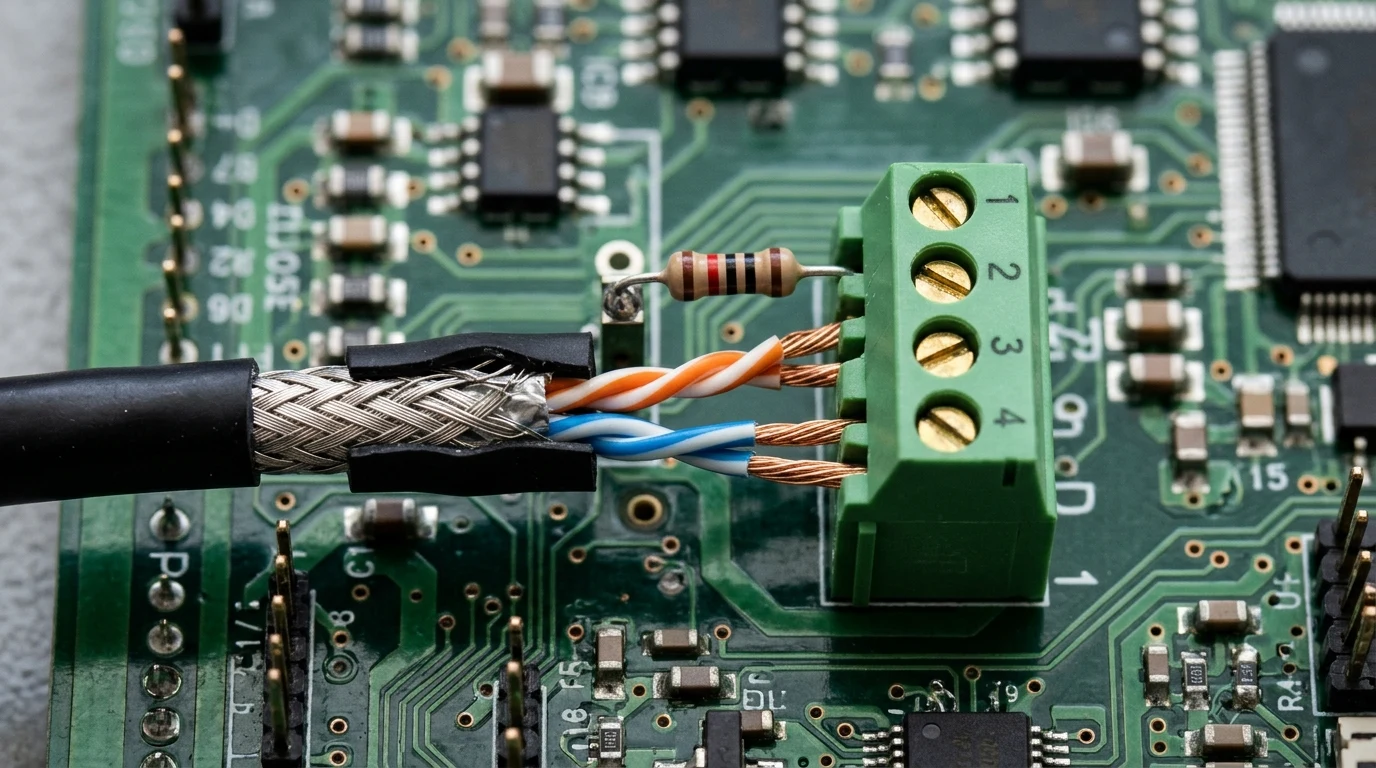
Shielding, Ground Loops, and Termination Resistors
While RS485 is differential, physical installation errors often undermine its reliability. Three physical rules must be respected:
The Ground Reference Conductor
A common misconception is that RS485 requires only two wires ( and ).
While differential transceivers measure relative voltage between and , their internal transistors can only tolerate common-mode voltages within a limited range (typically -7V to +12V DC relative to transceiver ground).
If an inverter and a monitoring computer operate on different grounding potentials, ground potential rise (GPR) during inverter switching can drive the common-mode voltage beyond +15V, destroying the serial transceiver IC.
Always run a third conductor for common signal ground (GND), or utilize galvanic opto-isolated USB-to-RS485 adapters.
Shield Drain Grounding
Use shielded twisted-pair cable (such as Belden 9841, Belden 3105A, or high-grade shielded Category 6).
The metallic foil shield must be grounded at one physical end only (typically at the monitoring server chassis). Grounding the shield at both ends creates a closed conductive loop that transforms the shield into an antenna for circulating ground currents.
Characteristic Impedance and Bus Line Termination
Electrical signals travel through copper conductor pairs at roughly sixty-six percent the speed of light. When high-speed square-wave edges encounter the open end of a transmission line, the sudden impedance discontinuity causes the electrical wavefront to reflect backward toward the transmitter, garbling packet data.
To prevent reflections, a 120-Ohm 1/4-Watt metal film resistor must be installed directly across the and terminals at the two physical endpoints of the daisy-chain bus. Many inverters include an internal DIP switch labeled “120Ω TERM” or “RT” that places this resistor into circuit when engaged.
The Modbus Protocol: Function Codes, Registers, and Data Decoding
Above the physical RS485 electrical layer runs the Modbus RTU (Remote Terminal Unit) application protocol.
Modbus RTU is an industrial, master-slave (client-server) architecture. A single master device (such as Home Assistant running on a mini PC) initiates queries, and one or more slave devices (inverters, charge controllers, BMS units) respond when addressed by their unique Slave ID (ranging from 1 to 247).
+-----------------------------------------------------------------------------------+
|               MODBUS RTU REQUEST & RESPONSE PACKET ANATOMY                        |
+-----------------------------------------------------------------------------------+
|                                                                                   |
|  MASTER REQUEST FRAME (Query Inverter for Battery Voltage):                       |
|  [Slave ID: 01] [Function: 04] [Start Reg: 00 64] [Count: 00 01] [CRC-16: 71 D5] |
|                                                                                   |
|  INVERTER RESPONSE FRAME:                                                         |
|  [Slave ID: 01] [Function: 04] [Byte Count: 02] [Data: 02 12]   [CRC-16: B8 4A]  |
|                                                                                   |
|  DECODING DATA BYTES (02 12 hex):                                                 |
|  0x0212 in Hexadecimal = 530 in Decimal                                           |
|  Apply Inverter Scale Factor (0.1V per LSB):                                      |
|  530 x 0.1V = 53.0 Volts DC                                                       |
|                                                                                   |
+-----------------------------------------------------------------------------------+
Holding Registers vs Input Registers
Modbus divides data storage into four discrete tables. In solar inverter communications, two tables dominate:
-
Input Registers (Object Type: Read-Only, Function Code 04): Used for volatile telemetry parameters that are generated by the inverter in real time:
- Solar panel array voltage and current
- AC grid frequency and inverter output wattage
- Internal heatsink and transformer temperatures
- Fault codes and operational warning flags
-
Holding Registers (Object Type: Read/Write, Function Codes 03, 06, 16): Used for configuration parameters and operational setpoints that can be altered by the user:
- Battery charging current limit (Amperes)
- Maximum grid export wattage
- Battery absorption and float voltage setpoints
- Generator auto-start trigger thresholds
Integer Scaling, Signed Values, and Endianness
A standard Modbus register stores a single 16-bit word (two bytes), representing values from 0 to 65,535 (unsigned) or -32,768 to +32,767 (signed).
Because Modbus does not natively transmit floating-point decimal numbers, inverter manufacturers utilize specific data encoding conventions:
The Scale Factor (Divisor)
To represent a voltage of 53.4V, the inverter stores the integer value 534 inside register 0x0064. The telemetry parser must apply a scale factor:
Two’s Complement for Bidirectional Current
Battery current flows in both directions: positive during solar charging, and negative during nighttime discharge.
Inverters store signed current in two’s complement format:
- A register value of
0x00A5represents (Charging). - A register value of
0xFF42represents a negative number. In 16-bit two’s complement,0xFF42translates to (Discharging).
Double-Word Registers and Endianness
Parameters that exceed 65,535 (such as total lifetime generated kilowatt-hours) are split across two consecutive 16-bit registers (32 bits total).
Engineers must identify the manufacturer’s byte order (Endianness):
- Big-Endian (Motorola format): Most significant byte stored first.
- Little-Endian (Intel format): Least significant byte stored first.
- If byte order is inverted during parsing, an energy reading of 1,250 kWh will decode as garbage numbers exceeding 40 million!
Hardware Bridges: Microcontrollers, Serial Converters, and Dedicated Gateways
To bridge the inverter’s serial RS485 communication lines into a local server, several hardware architectures are available:
+-----------------------------------------------------------------------------------+
|               LOCAL MODBUS HARDWARE INTEGRATION TOPOLOGIES                        |
+-----------------------------------------------------------------------------------+
|                                                                                   |
|  TOPOLOGY 1: DIRECT USB-TO-RS485 ADAPTER                                          |
|  [Inverter RS485 Port] ===(Shielded Pair)===> [USB-RS485 Adapter] ===> [Server USB|
|  Best for: Inverter located directly adjacent to Home Assistant server.           |
|                                                                                   |
|  TOPOLOGY 2: ETHERNET MODBUS TCP GATEWAY (Waveshare / Moxa)                       |
|  [Inverter RS485 Port] ===(RS485)===> [RS485-to-Ethernet Bridge] ===> [LAN Switch|
|  Best for: Inverters in detached outbuildings or off-grid power sheds.            |
|                                                                                   |
|  TOPOLOGY 3: WIRELESS ESP32 MICROCONTROLLER (ESPHome)                             |
|  [Inverter RS485 Port] ===(TTL)===> [MAX485 + ESP32] ===(Wi-Fi)===> [Home Assist|
|  Best for: Custom compact embedded integrations with local MQTT/API fail-safe.    |
|                                                                                   |
+-----------------------------------------------------------------------------------+
Industrial USB to Serial Converters
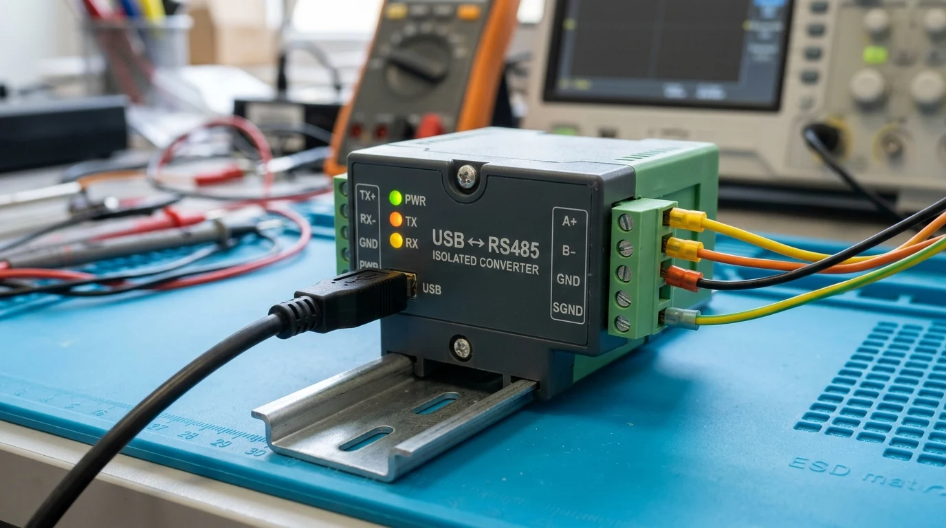
If the monitoring server (Raspberry Pi 4, Intel NUC, or mini PC) is situated within 5 meters of the inverter, an industrial USB-to-RS485 adapter provides the simplest, most stable connection:
- Require Genuine FTDI or Silicon Labs CP2102 Chipsets: Avoid cheap clone chips (such as generic counterfeit CH340s) that experience driver kernel panics under continuous high-frequency polling.
- Opto-Isolated Transceivers: Select adapters with built-in magnetic or optical isolation (such as the Waveshare USB-TO-RS485-B or DSD TECH SH-U10L). Galvanic isolation isolates the computer’s USB ground from the inverter chassis, preventing ground loops from burning server motherboards during lightning surges.
Microcontroller Firmware Gateways
For inverters located in remote battery sheds hundreds of feet from the living quarters:
- An Ethernet Modbus Gateway (such as the Waveshare RS485 to RJ45 Ethernet Converter or Moxa MB3180) translates raw Modbus RTU serial packets into standard Modbus TCP packets on Port 502.
- The gateway acts as a transparent network bridge, allowing Home Assistant to query the inverter over standard Cat6 Ethernet cables or long-range directional Wi-Fi links with zero packet loss.
Home Assistant Integration and Real-Time Automation Logic
Once the physical RS485 serial connection is verified, Home Assistant can ingest raw inverter telemetry directly using its native core Modbus integration.
Direct YAML Polling Configuration
Below is a production-grade configuration snippet for a standard hybrid inverter (configured for a Waveshare USB-to-RS485 converter mounted at /dev/ttyUSB0):
# configuration.yaml
modbus:
  - name: solar_inverter_bus
    type: serial
    method: rtu
    port: /dev/ttyUSB0
    baudrate: 9600
    stopbits: 1
    bytesize: 8
    parity: N
    timeout: 1
    delay: 0.1
    sensors:
      - name: "Solar PV1 Voltage"
        unique_id: solar_pv1_voltage
        slave: 1
        address: 30001
        input_type: input
        unit_of_measurement: "V"
        device_class: voltage
        state_class: measurement
        scale: 0.1
        precision: 1
        scan_interval: 2

      - name: "Battery Charge/Discharge Current"
        unique_id: battery_bus_current
        slave: 1
        address: 30015
        input_type: input
        unit_of_measurement: "A"
        device_class: current
        state_class: measurement
        scale: 0.1
        precision: 1
        data_type: int16
        scan_interval: 1

      - name: "Inverter Active AC Output Power"
        unique_id: inverter_ac_output_power
        slave: 1
        address: 30022
        input_type: input
        unit_of_measurement: "W"
        device_class: power
        state_class: measurement
        scale: 1.0
        scan_interval: 1
Notice the critical parameters:
data_type: int16forces Home Assistant to evaluate the 16-bit register as a signed two’s complement integer, correctly displaying negative Amps when the battery is discharging.scan_interval: 1updates the AC output wattage every second—providing instantaneous real-time visibility.
Automated Dynamic Load Shedding Sequences
With sub-second local telemetry established, Home Assistant transforms into an active energy manager.
Consider this real-world automation script that prevents an off-grid inverter from tripping during sudden overload events:
# automations.yaml
- alias: "Emergency Load Shedding on Inverter High Power"
  trigger:
    - platform: numeric_state
      entity_id: sensor.inverter_ac_output_power
      above: 11000
      for:
        seconds: 3
  condition:
    - condition: state
      entity_id: switch.water_heater_contactor
      state: "on"
  action:
    - service: switch.turn_off
      target:
        entity_id: switch.water_heater_contactor
    - service: notify.homestead_alerts
      data:
        title: "⚡ Load Shed Triggered"
        message: "Inverter exceeded 11kW! Domestic water heater contactor disengaged automatically."
If an induction cooktop and clothes dryer engage simultaneously while the electric water heater is running, the inverter’s power sensor crosses 11,000 Watts. Within three seconds, Home Assistant commands a dry-contact relay to disconnect the water heater, dropping power demand by 4,500 Watts and averting an inverter blackout.
Complete Off-Grid Solar Local Monitoring Commissioning Checklist
To guarantee reliable, maintenance-free local monitoring across the 25-year operational life of your solar equipment, execute this commissioning checklist:
+-----------------------------------------------------------------------------------+
|               LOCAL MODBUS TELEMETRY COMMISSIONING CHECKLIST                      |
+---+-------------------------------------------------------------------------------+
|   | 1. PHYSICAL CABLING & DIFFERENTIAL INTEGRITY                                  |
| [ ] High-grade twisted-pair shielded cable (Belden 9841 or Cat6 STP) installed.  |
| [ ] Signal ground conductor landed to prevent common-mode voltage breakdown.      |
| [ ] Shield foil grounded at server end only (float shield at inverter chassis).   |
| [ ] 120-Ohm metal film termination resistor installed at both ends of bus.       |
+---+-------------------------------------------------------------------------------+
|   | 2. SERIAL HARDWARE & CONVERTER VERIFICATION                                   |
| [ ] Optically isolated USB-to-RS485 adapter used (FTDI or Silicon Labs chipset).  |
| [ ] Serial port permissions configured in Linux host (dialout group membership).  |
| [ ] Inverter Baud Rate, Parity, Data Bits, and Stop Bits matched to master config.|
| [ ] Inverter unique Slave ID confirmed (Default typically 1 or 2).                |
+---+-------------------------------------------------------------------------------+
|   | 3. PROTOCOL & REGISTER PARSING AUDIT                                          |
| [ ] Verify Input Registers vs Holding Registers mapping per manufacturer manual.  |
| [ ] Confirm mathematical scale factors (0.1x / 0.01x) applied to each entity.     |
| [ ] Verify signed two's complement decoding for bidirectional battery currents.    |
| [ ] Confirm 32-bit big-endian / little-endian byte ordering on kWh accumulation.  |
+---+-------------------------------------------------------------------------------+
|   | 4. AUTOMATION & RESILIENCE VALIDATION                                         |
| [ ] Bench-test physical internet disconnect; verify telemetry operates 100% local.|
| [ ] Test dynamic load-shed automation under simulated high-power load spikes.     |
| [ ] Configure automated alert for serial communication timeouts (>15 seconds).    |
+---+-------------------------------------------------------------------------------+
By liberating your energy infrastructure from fragile third-party cloud architectures, you transform your off-grid solar installation into an autonomous, resilient power plant capable of sub-second intelligent decision-making regardless of whether the outside world is connected or completely offline.