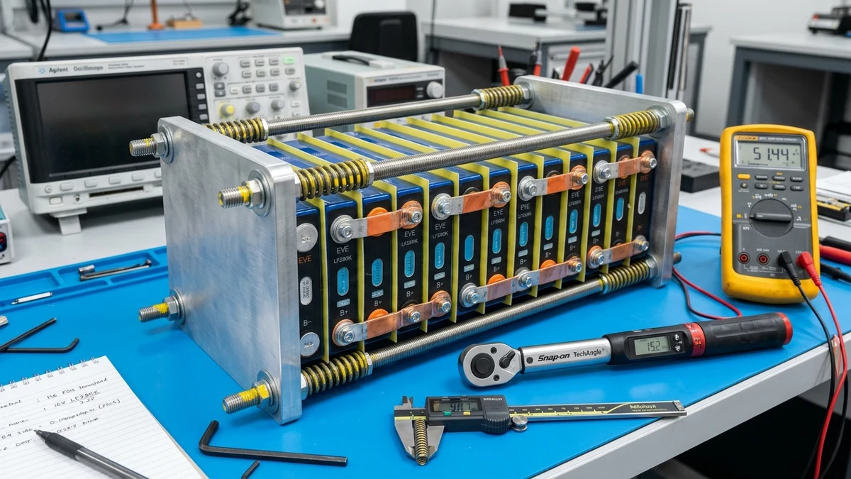
Prismatic lithium iron phosphate (LiFePO4) cells represent the gold standard for DIY off-grid energy storage, marine electrical systems, and commercial battery banks. When hobbyists unbox raw cells—such as the ubiquitous EVE LF280K, LF304, or CATL 302Ah modules—they often view them as solid, static blocks of aluminum. In reality, a prismatic battery cell is a dynamic electrochemical pressure vessel that physically expands and contracts with every charge and discharge cycle.
Factory datasheets from Tier-1 manufacturers like EVE Energy, CATL, and REPT unequivocally specify that prismatic cells must be operated under continuous mechanical compression. Despite this clear instruction, uncompressed battery banks remain common in DIY builds. Without proper clamping, prismatic cells suffer from internal layer delamination, uneven current distribution, localized impedance spikes, and premature capacity fade, reducing cycle life from over 6,000 cycles down to fewer than 2,500.
This engineering guide examines the physics of prismatic cell breathing, breaks down manufacturer pressure specifications, presents the mathematical formulas required to size dynamic spring fixtures, and provides an actionable blueprint for constructing a laboratory-grade compression jig.
Electrochemical Physics of Prismatic Cell Breathing and Delamination
To understand why mechanical compression is non-negotiable, we must examine the micro-scale mechanics occurring inside the aluminum casing during cycling.
Intercalation Strain and Anode Swelling
A prismatic LiFePO4 cell consists of wound or stacked layers of positive electrodes (lithium iron phosphate coated onto aluminum foil), separators (microporous polyethylene or polypropylene), and negative electrodes (synthetic graphite coated onto copper foil), all submerged in a liquid organic carbonate electrolyte.
During the charging process, lithium ions de-intercalate from the olivine cathode lattice and migrate through the electrolyte to intercalate between the graphene sheets of the graphite anode. This physical insertion of lithium ions forces the graphite crystal lattice to expand by approximately 10% to 12% along its c-axis:
On a macroscopic level, a typical 280Ah to 314Ah cell (with a nominal thickness of 71.5 mm to 72.0 mm) increases in thickness by 1.0 mm to 1.8 mm as it transitions from 0% to 100% State of Charge (SoC). Over a 16-cell series pack (16S 48V configuration), the cumulative pack length increases by 16 mm to nearly 28 mm during a full bulk charge. This cyclic dimensional variation is known as cell breathing.
Mechanism of Delamination in Uncompressed Packs
When prismatic cells are allowed to cycle freely without external clamping:
- Electrode Separation: As the graphite anode contracts during discharge, the active material layer shrinks away from the current collector foil and adjacent separator.
- Macroscopic Voids and Gas Trapping: Microscopic air or gas bubbles generated during normal Solid Electrolyte Interphase (SEI) maintenance become trapped between the separated layers, displacing the liquid electrolyte.
- Current Crowding and Dendrite Growth: Areas deprived of electrolyte contact lose ionic conductivity. Current is forced through the remaining connected surface area, causing localized current crowding, high local overpotentials, and microscopic lithium plating.
- Permanent Casing Bulging: Repetitive mechanical flexing causes work-hardening and plastic deformation of the 0.8mm-thick aluminum cell casing. Once bulged, the cell cannot recover its flat geometry, resulting in permanently elevated internal resistance ().
UNCOMPRESSED CELL CYCLE:
Charge Swelling ──> Anode Expansion ──> Mechanical Casing Flex
      ▲                                        │
      │                                        ▼
Delamination <── Electrolyte Void Formation <── Discharge Contraction
EVE and CATL Manufacturer Factory Compression Specifications
Major cell manufacturers perform standardized life-cycle testing under strictly controlled mechanical fixtures. The factory datasheets for commercial cells specify both initial clamping force and operating pressure tolerances.
| Manufacturer & Model | Nominal Capacity | Cell Dimensions (W × T × H) | Recommended Clamping Force | Surface Pressure Equivalent | Rated Cycle Life (at 25°C, 0.5C) |
|---|---|---|---|---|---|
| EVE LF280K (v3) | 280 Ah | 173.7 × 71.7 × 207.2 mm | 300 kgf ± 20 kgf (3,000 N) | 12.1 psi (83.4 kPa) | 6,000 cycles to 80% SOH |
| EVE LF304 | 304 Ah | 173.7 × 72.0 × 207.5 mm | 300 kgf ± 20 kgf (3,000 N) | 12.0 psi (82.7 kPa) | 6,000 cycles to 80% SOH |
| CATL 302Ah | 302 Ah | 174.0 × 71.5 × 207.0 mm | 300 kgf to 400 kgf (3,000–4,000 N) | 12.1 to 16.1 psi (83.4–111.0 kPa) | 6,000 cycles to 80% SOH |
| REPT 280Ah | 280 Ah | 173.9 × 71.5 × 207.2 mm | 300 kgf ± 25 kgf (2,940 N) | 11.9 psi (82.0 kPa) | 5,500 cycles to 80% SOH |
| CALB 230Ah | 230 Ah | 173.9 × 53.8 × 200.3 mm | 250 kgf ± 20 kgf (2,450 N) | 10.4 psi (71.7 kPa) | 4,500 cycles to 80% SOH |
Converting Force to Surface Pressure
The total force () exerted on the cell face is distributed over the broad surface area () of the cell’s broad side:
For an EVE LF280K cell:
- Width () = 173.7 mm = 6.839 inches
- Height below terminal shoulder () = 204.0 mm = 8.031 inches
- Surface Area () =
- Target Force () =
Dividing total force by surface area yields:
This confirms why commercial manufacturers target 12 to 14 psi across the broad face of standard form-factor prismatic cells.
Pitfalls of Rigid Static Clamping
A dangerous misconception in DIY battery building is that tightening threaded steel rods against rigid endplates without springs creates proper compression. Rigid static bolting is worse than no compression at all.
Steel threaded rods exhibit minimal mechanical compliance. When an unyielding fixture is torqued down on cells at 30% or 50% SoC:
- Extreme Pressure Spikes at Full Charge: As the battery charges to 100% SoC and expands by 1.5 mm per cell, the rigid rods cannot stretch appreciably. The internal pressure escalates exponentially, exceeding 800 kgf to 1,200 kgf (>40 psi). This crushes the microscopic pore structure of the polyethylene separator, impeding lithium ion transport and causing localized thermal hot spots.
- Loss of Compression at Low SoC: As the pack discharges down to 0% to 20% SoC, the cells contract back to their baseline dimensions. Because steel threaded rods undergo negligible strain, the mechanical clamping force drops to zero, allowing internal delamination during high-rate discharge.
To maintain a steady 300 kgf across the full state-of-charge spectrum, the fixture must incorporate dynamic compliance through calibrated springs.
Structural Fixture Materials and Rigid Endplate Engineering
A compression jig is only as effective as the rigidity of its endplates. Because 300 kgf (661 lbf) of force is applied across the pack, thin or flexible materials will bow outward in the center.
Endplate Deflection and Uneven Core Pressure
If an endplate flexes by even 0.5 mm in the center, the outer perimeter of the cell receives maximum clamping force while the core of the cell experiences near-zero compression. This causes convex core bulging and uneven current density across the electrode jelly-roll.
FLEXIBLE ENDPLATE (BAD):
  [Rod] ───►  /═══════════\  ◄─── [Rod]
             |  Cell Pack  |
  [Rod] ───►  \═══════════/  ◄─── [Rod]
      High perimeter force, ZERO core pressure!

RIGID ENDPLATE (GOOD):
  [Rod] ───►  ║═══════════║  ◄─── [Rod]
             ║  Cell Pack  ║
  [Rod] ───►  ║═══════════║  ◄─── [Rod]
      100% uniform 12.0 psi core and perimeter force!
Material Selection Matrix
| Material | Minimum Thickness | Yield Strength | Weight (16S Pair) | Evaluation for Battery Jigs |
|---|---|---|---|---|
| 6061-T6 Aluminum Plate | 12.0 mm (0.50 in) | 276 MPa (40 ksi) | ~4.2 kg (9.2 lbs) | Recommended. Excellent strength-to-weight ratio, easy to drill, zero magnetic interaction, high thermal conductivity. |
| A36 Structural Carbon Steel Plate | 6.0 mm (0.25 in) | 250 MPa (36 ksi) | ~5.8 kg (12.8 lbs) | Recommended for budget builds. Extremely rigid, low deflection, but requires powder-coating or paint to prevent rust. |
| 304 Stainless Steel Plate | 6.0 mm (0.25 in) | 215 MPa (31 ksi) | ~5.9 kg (13.0 lbs) | High-end marine. Corrosion-proof, non-magnetic, highly rigid. |
| Plywood / MDF / Birch Core | Not Recommended | Under 30 MPa (under 4 ksi) | ~2.5 kg (5.5 lbs) | Unacceptable. High creep, moisture absorption, prone to splitting and catastrophic bowing over time. |
| Extruded 2020/2040 Aluminum | Not Recommended | Variable | ~1.8 kg (4.0 lbs) | Unacceptable as endplates. Twists and flexes under central point loads unless heavily reinforced. |
Tie-Rod Specifications
Four tie-rods—positioned at the four corners of the endplate—are standard for distributing clamping force uniformly.
- Thread Size: M10 (metric) or 3/8-16 (UNC) high-tensile threaded all-thread.
- Material Grade: 304 Stainless Steel or Grade B7 zinc-plated alloy steel.
- Tension per Rod: per rod.
- Safety Factor: Standard 3/8-16 Grade B7 rod provides a tensile yield capacity exceeding 6,000 lbf, delivering a safety factor greater than 35:1 against thread stripping.
Calculating Spring Deflection for Dynamic Force Regulation
The core engineering challenge is selecting springs that deliver exactly 75 kgf (735.5 N) of force per corner rod while accommodating the cumulative thermal and lithiation breathing of the cell bank.
Physics of Spring Deflection (Hooke’s Law)
The force generated by a compression spring is governed by Hooke’s Law:
Where:
- = Required force per spring ()
- = Spring rate (spring constant, measured in or )
- = Compression displacement (deflection from free length, in )
Calculating Cell Pack Breathing Amplitude
For a 16-cell series bank (16S 48V pack) utilizing 280Ah cells:
- Baseline expansion per cell (0% to 100% SoC):
- Cumulative pack breathing ():
Because the fixture is clamped across the entire 16-cell stack, each spring must absorb this expansion without allowing force to spike outside the factory tolerance range of 280 kgf to 320 kgf (70 kgf to 80 kgf per rod).
To minimize the percentage change in force () across the 19.2 mm pack expansion, you must choose springs with:
- A relatively low spring rate ()
- A large initial deflection ()
If a very stiff spring is compressed by only 2 mm to reach 75 kgf, adding 19.2 mm of pack expansion will cause the force to increase tenfold, destroying the cells. Conversely, if a long, compliant spring is compressed by 25 mm to achieve 75 kgf, an additional 1.2 mm of breathing per spring (or using dual-ended springs) maintains force within tight tolerances.
Spring Selection: ISO 10243 Die Springs vs Belleville Washers
SPRING COMPARISON FOR COMPRESSION JIGS:

1. Heavy-Duty Die Springs (ISO 10243):
   ├── Large linear travel range (15mm to 30mm)
   ├── Predictable linear spring rate (k)
   ├── Highly recommended for multi-cell packs (8S, 16S)
   └── Visual inspection of deflection with digital calipers

2. Belleville Disc Springs (Conical Washers):
   ├── Extremely compact axial footprint
   ├── Very high load capacity in small space
   ├── Very short stroke (0.5mm to 1.5mm per disc)
   └── Requires stacking in series (alternating) to achieve breathing compliance
Numerical Engineering Example: 4S vs 16S Fixtures
For a compact 4S 12V pack:
- Total pack expansion: .
- Target force per rod: (75 kgf).
- Target spring rate (): Sizing for initial deflection:
When the 4S pack expands by 4.8 mm during full charge:
- New deflection: .
- New force per rod: (98.9 kgf).
- Total pack force: .
This remains well within the safe temporary envelope of CATL and EVE cells (peak tolerance up to 400 kgf). For larger 16S packs, dual springs per rod (one at each endplate) or higher-travel die springs ensure the load variation remains within ±10%.
Inter-Cell Dielectric Isolation with FR4 Epoxy Fiberglass
The outer metallic shell of prismatic LiFePO4 cells is fabricated from deep-drawn aluminum. While the exterior is wrapped in a thin blue polyethylene terephthalate (PET) heat-shrink sleeve, this factory film must never be relied upon for primary electrical insulation.
Why PET Film Fails Under Compression
- Vibration Abrasion: As cells breathe cyclically, the microscopic relative movement between adjacent cell casings abrades the thin 0.08mm to 0.12mm PET wrap.
- Dielectric Breakdown: In a 48V (16S) nominal pack, charging voltages reach 58.4V. If the PET sleeves wear through on two adjacent cells with opposing polarity potentials, a dead short circuit occurs directly across the cell casings.
- Casing Voltage Potential: On most prismatic cells, the aluminum casing is electrically connected to the positive terminal or floats at a hazardous mid-potential.
DANGER: ABRASION LEADING TO CASING ARC
[Cell N (-) Shell] <── Abraded PET ──> [Cell N+1 (+) Shell]
                     ▲
            DEAD SHORT-CIRCUIT!
The FR4 Epoxy G10 Advantage
The definitive solution is inserting rigid, precision-cut FR4 (G10) epoxy fiberglass sheets between every pair of cells and between the end cells and the metal endplates.
- Recommended Thickness: 0.5 mm to 1.0 mm (0.020 to 0.040 in).
- Dielectric Strength: (providing over 10,000V of electrical isolation for a 0.5mm sheet).
- Compressive Modulus: High mechanical strength under static loads exceeding 400 MPa, ensuring zero creep or thinning under 14 psi clamping pressure.
- Thermal Rating: Class B or F ( to continuous), completely immune to battery operating temperatures.
[!CAUTION] Never use soft closed-cell EVA foam, neoprene, or bubble wrap between cells in a compression jig. Under 300 kgf of force, soft elastomers permanently deform and compress to near-zero thickness, releasing all rod spring tension within days.
Step-by-Step Fixture Assembly and Tension Calibration
Building a laboratory-grade compression fixture requires systematic execution to prevent uneven shear loads and terminal stress.
EXPLODED FIXTURE ASSEMBLY:
[Nut + Washer]
     │
[Die Spring]
     │
[Washer]
     │
[12mm Aluminum Endplate]
     │
[FR4 Insulator Sheet]
     │
[Cell 1] ── [FR4] ── [Cell 2] ── [FR4] ── ... ── [Cell 16]
     │
[FR4 Insulator Sheet]
     │
[12mm Aluminum Endplate]
     │
[Washer + Locknut]
Required Hardware Checklist (16S Pack)
- 2× 6061-T6 Aluminum Endplates ()
- 17× FR4 Epoxy Fiberglass Divider Sheets ()
- 4× M10 or 3/8-16 Grade 304 Stainless Steel Threaded Rods (length = pack length + 150 mm)
- 4× Heavy-Duty Yellow or Blue Die Springs (calibrated rate, e.g., 40–50 N/mm)
- 8× Heavy-duty thick fender washers (hardened stainless steel)
- 8× M10 or 3/8-16 stainless hex nuts (with Nyloc locking nuts or double jam-nuts)
- High-resolution digital vernier caliper (0.01 mm resolution)
- Torque wrench (optional, for cross-checking)
Fixture Assembly Protocol
Pre-Assembly Inspection and Pack Alignment
- Verify all cells are at an identical storage State of Charge (30% to 50% SoC, nominal voltage 3.28V to 3.30V). Clamping fully charged cells makes initial spring calibration inaccurate.
- Clean all cell surfaces with isopropyl alcohol (99%) to eliminate abrasive particles that could puncture cell films.
- Stand the cells upright on an electrically non-conductive, flat surface (such as a 10mm high-density polyethylene plate or rubber ESD mat).
- Place an FR4 epoxy divider sheet between every adjacent cell, ensuring total coverage of the broad aluminum faces.
Installing Endplates and Guide Rods
- Place an FR4 sheet on each outer face of the first and sixteenth cells to isolate the battery terminals from the aluminum endplates.
- Position the two 12mm 6061-T6 aluminum endplates against the front and rear of the pack.
- Insert the four threaded rods through the corner mounting holes. Ensure rods do not touch the active blue PET foil of the battery cells; maintain at least a 5mm air gap between rods and cell sidewalls.
- Thread a flat washer and hex nut onto the fixed end of each rod.
Spring Installation and Zero-Deflection Measurement
- Slide a heavy-duty washer over the tensioning end of each rod, followed by the die spring, a second heavy washer, and the adjustment nut.
- Hand-tighten all four nuts until the springs just make contact with the washers without compressing.
- Use your digital caliper to measure and record the uncompressed free length () of each of the four springs.
Calibrating Dynamic Spring Deflection
- Determine the target compressed length () based on the calibrated spring rate ():
- Tighten the adjustment nuts in a diagonal cross-pattern (top-left, bottom-right, top-right, bottom-left), turning each nut one full revolution at a time.
- Continuously measure the spring length on all four corners with the digital caliper until all four springs match within ±0.2 mm.
- Thread on a secondary jam-nut or engage the nylon insert on each rod to lock the calibrated position permanently.
Long-Term Maintenance and Busbar Strain Relief
Once the compression fixture is assembled, the mechanical integration with electrical components requires careful management.
Flexible Braided Busbars vs Solid Copper Plates
Because the battery pack breathes by 15 mm to 20 mm across cycles, solid, rigid copper busbar plates must never be installed on a compressed pack without expansion bends.
If flat, unyielding copper bars are bolted across the battery terminals:
- When the pack expands during bulk charging, the distance between terminal posts increases.
- The rigid busbar exerts immense mechanical shear force directly onto the welded laser terminal studs.
- Over time, this shear stress fractures the internal terminal seal, causing electrolyte leakage, micro-shorts, and catastrophic cell failure.
BUSBAR EXPANSION TOLERANCE:

Solid Flat Busbar (BAD):
  [Terminal A] ═══ Rigid Copper Plate ═══ [Terminal B]
  (Expansion shears terminal welds off the casing!)

Flexible U-Bend / Laminated Busbar (GOOD):
                 ┌─────┐
                 │     │  <── Expansion loop absorbs cell breathing
  [Terminal A] ──┘     └── [Terminal B]
  (Zero mechanical shear transferred to terminal posts!)
Always install flexible braided copper busbars or solid copper busbars with stamped U-shaped expansion bends. This allows each cell to expand and contract smoothly within its calibrated spring-loaded fixture without transferring axial strain to the sensitive electrical connections.
Technical Summary
Operating prismatic LiFePO4 cells without mechanical compression sacrifices up to 60% of their potential cycle life. By designing a dynamic fixture using 12mm 6061-T6 aluminum endplates, FR4 dielectric dividers, and calibrated ISO die springs delivering 300 kgf ± 20 kgf (12 to 14 psi), off-grid engineers eliminate delamination, prevent premature capacity fade, and ensure safe, reliable energy storage over decades of heavy cycling.