The electrification of personal transportation has reached off-grid homesteads, remote ranches, and solar-powered cabins. Driving an electric vehicle (EV) powered entirely by self-generated solar energy represents the pinnacle of personal energy independence: zero fuel costs, zero trips to commercial filling stations, and zero reliance on vulnerable utility infrastructure.
However, an electric vehicle is not just another household appliance. It is an industrial-scale electrical load with an enormous energy appetite.
A modern electric pickup or SUV (such as a Ford F-150 Lightning, Rivian R1T, or Tesla Cybertruck) carries an onboard battery pack between 90 and 135 kilowatt-hours (kWh)—three to six times larger than the entire stationary battery bank powering a typical off-grid home.
If an EV driver connects a standard, unmanaged 48-Amp Level 2 charging station (drawing 11,520 Watts continuously at 240V), the charging station will immediately monopolize the inverter’s capacity. If a central heat pump or well pump kicks on simultaneously, the inverter will overload and plunge the home into darkness. Worse, if left charging unattended overnight, the EV will drain the home’s stationary battery bank to zero percent cutoff before morning.
To charge an electric vehicle safely on an off-grid solar system, the charging infrastructure must be dynamically managed.
This technical guide examines the communication protocol governing Level 2 charging, details real-time solar diversion via current transformer (CT) monitoring, analyzes round-trip thermodynamic conversion losses, and outlines the automation logic needed to protect domestic battery reserves.
Executive Summary: The EV Sizing Reality
Can an off-grid solar system charge an electric vehicle? Yes, provided the charger operates as a modulated follower rather than an unmanaged brute load:
+-----------------------------------------------------------------------------------+
|               OFF-GRID LEVEL 2 EV CHARGING AT A GLANCE                            |
+-----------------------------------------------------------------------------------+
|  1. Uncontrolled Hazard: 48A charging draws 11.5kW continuous, draining a 30kWh   |
|     homestead battery in 2.6 hours and risking immediate inverter overload.       |
|                                                                                   |
|  2. Dynamic Throttling: Smart EVSEs modulate charging from 6A (1.4kW) to 48A     |
|     (11.5kW) in 1-Amp increments via J1772 / NACS Control Pilot PWM signaling.   |
|                                                                                   |
|  3. Solar Divert Architecture: CT clamps measure real-time PV generation; the     |
|     charger matches vehicle draw strictly to surplus solar watts above home loads.|
|                                                                                   |
|  4. Battery Preservation Logic: Charging is locked out until the home battery      |
|     reaches 85% to 90% SOC, preventing transportation from cannibalizing backup.  |
+-----------------------------------------------------------------------------------+
By transitioning from fixed-rate charging to dynamic solar-following, an EV becomes an asset: an enormous thermal and electrochemical dump load that captures excess solar energy that would otherwise be curtailed once the home battery is full.
The J1772 Communication Protocol: How Chargers Throttle Amperage
A common misconception among homeowners is that a Level 2 wall unit (EVSE) converts or regulates electrical power internally. In reality, a Level 2 EVSE is essentially a smart safety contactor.
AC line voltage passes directly through the wall unit into the vehicle’s onboard charger. The wall unit dictates how much current the vehicle is permitted to draw through a low-voltage communication channel known as the Control Pilot (CP) line.

Pulse Width Modulation (PWM) Duty Cycle Mathematics
Under the SAE J1772 and IEC 61851-1 standards, the EVSE generates a 1,000 Hz, 12-Volt square wave on the Control Pilot pin:
- When the vehicle connects, the pilot voltage drops to 9V (vehicle detected) and then 6V (vehicle ready to charge).
- The EVSE commands the maximum allowable current by altering the duty cycle () of the 1kHz square wave:
For target currents between 6 Amperes and 51 Amperes ():
For target currents between 51 Amperes and 80 Amperes ():
+-----------------------------------------------------------------------------------+
|                 SAE J1772 CONTROL PILOT DUTY CYCLE TO CURRENT MAPPING             |
+-----------------------------------------------------------------------------------+
| Duty Cycle (%) | Allowable Current (Amps) | Power at 240V AC | Off-Grid Suitability|
+----------------+--------------------------+------------------+---------------------+
| 10.0%          | 6 Amperes (Minimum)      | 1,440 Watts      | Small PV Surplus    |
| 16.6%          | 10 Amperes               | 2,400 Watts      | Overcast Day        |
| 26.6%          | 16 Amperes               | 3,840 Watts      | Moderate Solar      |
| 40.0%          | 24 Amperes               | 5,760 Watts      | Strong Midday Sun   |
| 53.3%          | 32 Amperes               | 7,680 Watts      | Large Array Surplus |
| 66.6%          | 40 Amperes               | 9,600 Watts      | Maximum 12kW Invert.|
| 80.0%          | 48 Amperes               | 11,520 Watts     | Utility Grid Only   |
+----------------+--------------------------+------------------+---------------------+
The 6-Amp Physical Boundary
Notice the critical lower boundary: the J1772 standard does not allow charging below 6 Amperes.
If your solar array surplus drops below 1,440 Watts (6A at 240V), the EVSE cannot throttle down to 3A or 4A. It must either:
- Temporarily pause charging (setting the pilot to 100% steady DC).
- Or allow the deficit (e.g., 400W) to be drawn temporarily from the home’s stationary battery bank until solar generation recovers.
Dynamic Solar Following: Real-Time CT Clamp Load Diverting
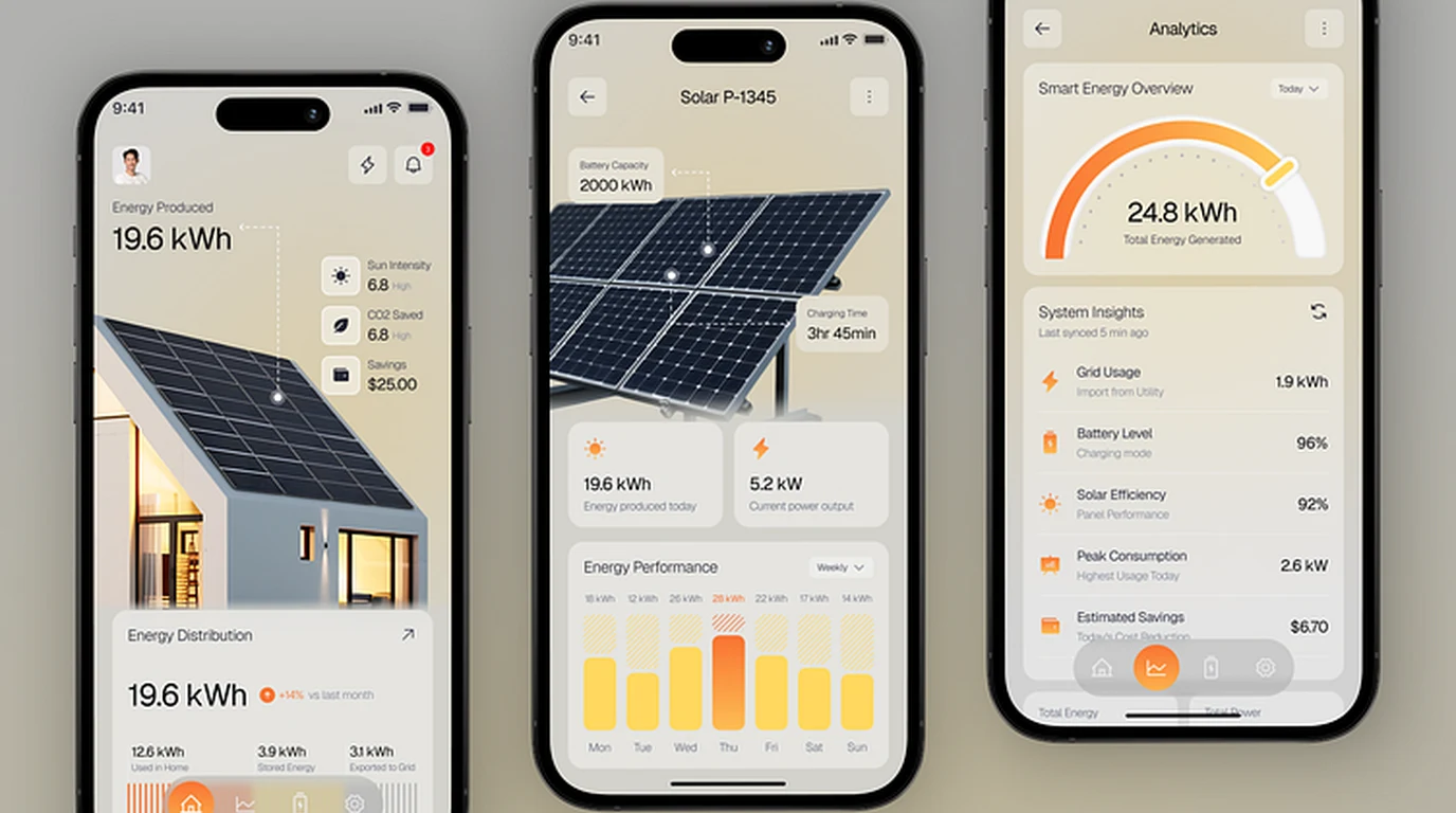
To charge an electric car without draining the home battery, smart EV chargers (such as the Emporia Smart EVSE, Wallbox Pulsar Plus, or OpenEVSE) utilize current transformers (CT clamps) installed inside the main electrical panel.
The Energy Balance Algorithm
Every 500 to 1,000 milliseconds, the EVSE’s microprocessor recalculates the net household energy balance:
Where:
- is real-time solar production.
- is the combined draw of lighting, refrigeration, cooking, and water pumps.
- is the power allocated to charging the home’s stationary batteries.
+-----------------------------------------------------------------------------------+
|                     REAL-TIME SOLAR FOLLOWING DYNAMICS                            |
+-----------------------------------------------------------------------------------+
|  12:00 PM (Clear Sun):                                                            |
|  • Solar PV Output: 9,200 Watts                                                   |
|  • House Baseline Load: 1,200 Watts                                               |
|  • Home Battery: 100% Full (0W needed)                                            |
|  • Surplus Available: 8,000 Watts (33.3A at 240V)                                 |
|  • EVSE Action: Sets Pilot PWM to 55% Duty Cycle ---> Car Charges at 33A (7.9kW)  |
|                                                                                   |
|  12:15 PM (Passing Cloud + Well Pump Starts):                                     |
|  • Solar PV Drops to: 4,500 Watts                                                 |
|  • Well Pump Starts (+2,400W): House Total = 3,600 Watts                          |
|  • Surplus Drops to: 900 Watts (Below 6A Minimum!)                               |
|  • EVSE Action: Instantly Pauses Charging (0A) in < 1 Second!                     |
|  • Result: Zero drain on home battery; zero inverter overload!                   |
+-----------------------------------------------------------------------------------+
By continuously tracking the instantaneous power delta, the EV charger behaves like an automated water spillway: absorbing every excess watt of solar generation during peak production hours while stepping out of the way the moment domestic appliances demand power.
Thermodynamic Efficiency: Direct Daytime Charging vs Battery Cycling
One of the most consequential considerations in off-grid EV integration is round-trip electrical efficiency.
The High Penalty of Double Energy Storage
Some off-grid homeowners assume they can simply let their solar panels charge a massive 60kWh home battery bank during the day, and then use that stationary battery bank to recharge their electric vehicle overnight.
Thermodynamically, this double-cycling strategy incurs severe energy losses:
+-----------------------------------------------------------------------------------+
|                 ROUND-TRIP EFFICIENCY CASCADE COMPARISON                          |
+-----------------------------------------------------------------------------------+
|  PATH A: DIRECT DAYTIME SOLAR CHARGING                                            |
|  • Solar Panel DC Output                                    = 100.0%              |
|  • Hybrid Inverter DC-to-AC Inversion (94% efficiency)      =  94.0%              |
|  • Level 2 EVSE Wiring Conduction Loss (99% efficiency)     =  93.1%              |
|  • EV Onboard AC-to-DC Charger & Battery (89% efficiency)   =  82.8%              |
|  NET ROUND-TRIP EFFICIENCY                                  =  82.8% (17% Lost)   |
|                                                                                   |
|  PATH B: OVERNIGHT CHARGING VIA HOME BATTERY BANK                                 |
|  • Solar Panel DC Output                                    = 100.0%              |
|  • MPPT Charge Controller to 48V Battery (96% efficiency)   =  96.0%              |
|  • LiFePO4 Battery Coulombic Round-Trip (93% efficiency)    =  89.3%              |
|  • Inverter 48V DC-to-240V AC Inversion (92% efficiency)    =  82.1%              |
|  • EV Onboard AC-to-DC Charger & Battery (89% efficiency)   =  73.1%              |
|  NET ROUND-TRIP EFFICIENCY                                  =  73.1% (27% Lost)   |
+-----------------------------------------------------------------------------------+
Cycling solar electricity through a home battery bank before feeding an electric car incurs a 27% total round-trip loss compared to just 17% when charging directly during daylight hours.
Over the course of a year (driving 12,000 miles consuming ~3,600 kWh), direct solar charging preserves over 500 kilowatt-hours of precious energy—equivalent to fifty full days of household lighting and refrigeration!
Inverter Sizing and Main Service Protection
To safely accommodate an EV charger alongside standard household appliances, the off-grid inverter must be sized with adequate continuous headroom.
Minimum Inverter Capacity Thresholds
+-----------------------------------------------------------------------------------+
|               INVERTER SIZING RECOMMENDATIONS FOR EV CHARGING                     |
+-----------------------------------------------------------------------------------+
| Inverter Continuous Output | Maximum Recommended EV Rate | Domestic Load Headroom |
+----------------------------+-----------------------------+------------------------+
| 6.0 kW (e.g. EG4 6000XP)   | 16 Amps (3.8 kW)            | 2.2 kW (Minimal)       |
| 8.0 kW (e.g. Deye 8kW)     | 24 Amps (5.7 kW)            | 2.3 kW (Tight)         |
| 12.0 kW (e.g. Sol-Ark 12K) | 32 Amps (7.6 kW)            | 4.4 kW (Comfortable)   |
| 15.0 kW (e.g. Sol-Ark 15K) | 40 Amps (9.6 kW)            | 5.4 kW (Full Household)|
| 18.0 kW (e.g. EG4 18kPV)   | 48 Amps (11.5 kW)           | 6.5 kW (Uncompromised) |
+----------------------------+-----------------------------+------------------------+
For off-grid systems with inverters rated at 8kW or smaller, charging an EV at 32A or 48A is physically impossible without tripping overcurrent limits. Inverters under 10kW should be restricted to 16A to 24A maximum EV charging.
State of Charge (SOC) Interlocks and Smart Automation
The gold standard for off-grid EV charging is integrating the charger into a central energy management controller (such as Home Assistant, Victron Cerbo GX, or Sol-Ark Modbus RTU).
The Three-Tier Operational Logic
+-----------------------------------------------------------------------------------+
|                     THREE-TIER AUTOMATED CHARGING LOGIC                           |
+-----------------------------------------------------------------------------------+
|  TIER 1: Home Battery Reserve Priority (SOC < 80%)                                |
|  • EVSE State: LOCKED OUT (0 Amps).                                               |
|  • Purpose: 100% of solar generation is directed to replenishing domestic        |
|    batteries and running essential household refrigeration and well pumps.        |
|                                                                                   |
|  TIER 2: Solar Surplus Diversion (80% <= SOC < 95%)                               |
|  • EVSE State: DYNAMIC MODULATION (6A to 32A).                                    |
|  • Purpose: The car charges strictly from surplus solar wattage exceeding home    |
|    consumption, leaving a gentle 1kW to 2kW trickle to top off the home battery. |
|                                                                                   |
|  TIER 3: Maximum Dump Load Absorption (SOC >= 95%)                                |
|  • EVSE State: FULL THROTTLE (Up to 40A / 48A).                                   |
|  • Purpose: The home battery is fully saturated; the EV opens its onboard pack    |
|    to absorb all available solar energy, preventing panel curtailment.            |
+-----------------------------------------------------------------------------------+
Implementing Hardware Failsafes
Software can crash, and Wi-Fi networks can drop. To ensure an automation glitch never drains your battery bank in the middle of the night:
- Inverter Low-SOC Dry Contact Interlock: Wire the EVSE’s hardware enable/disable control terminals through a dry contact relay on your battery inverter.
- If the home battery bank drops beneath 60% SOC, the relay physically opens, cutting the EVSE pilot signal and stopping charging immediately regardless of software status.
Off-Grid EV Charging Commissioning Checklist
Before connecting your electric car to an off-grid solar installation, verify that your system satisfies this technical checklist:
+-----------------------------------------------------------------------------------+
|                     OFF-GRID EV CHARGING COMMISSIONING AUDIT                      |
+-----------------------------------------------------------------------------------+
| [X] Smart EVSE Hardware: Dynamic load-modulating charger supporting real-time     |
|     SAE J1772 pilot duty cycle throttling down to 6 Amps.                         |
|                                                                                   |
| [X] CT Clamp Monitoring: Current transformers installed on inverter main output   |
|     to monitor total household demand and prevent inverter overcurrent trips.     |
|                                                                                   |
| [X] Battery SOC Lockout: Automated control interlock preventing EV charging until  |
|     stationary home battery bank exceeds 80% to 85% state of charge.              |
|                                                                                   |
| [X] Daytime Charging Discipline: Prioritize vehicle charging between 10:00 AM     |
|     and 3:00 PM to capture 83% direct solar efficiency and avoid battery cycling.|
|                                                                                   |
| [X] Inverter Headroom: Minimum 4kW of unallocated inverter capacity reserved for   |
|     starting domestic well pumps and HVAC compressors during vehicle charging.    |
|                                                                                   |
| [X] Hardware Failsafe: Hardwired inverter dry-contact disconnect to cut charging  |
|     automatically if stationary battery drops beneath 60% capacity.               |
+-----------------------------------------------------------------------------------+
By engineering dynamic solar-following into your charging infrastructure, an electric vehicle transforms from a threatening electrical liability into the ultimate off-grid asset—delivering clean, fuel-free transportation entirely powered by the sun.
