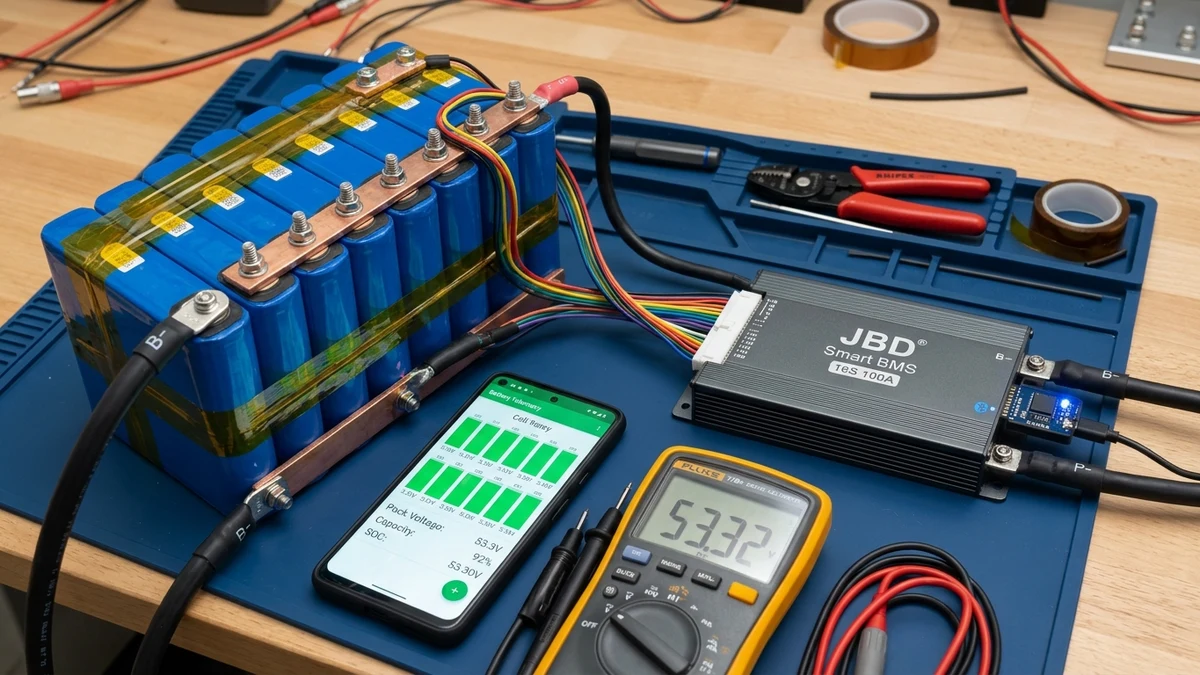
The JBD (Jiabaida) Smart Battery Management System—also widely branded and supported under the Overkill Solar ecosystem—is one of the most reliable, field-tested BMS platforms for DIY lithium iron phosphate (LiFePO4) energy storage. Available in 4S (12V), 8S (24V), and 16S (48V) architectures with continuous current ratings from 100A to 200A, JBD units offer robust low-side solid-state switching, programmable protection thresholds, Bluetooth telemetry, and open communication protocols.
However, improper installation or misconfigured factory firmware parameters frequently lead to nuisance inverter shutdowns, fried balance transistors, or undetected cell drift.
This engineering guide provides a rigorous setup procedure for the JBD 16S Smart BMS. We walk through physical terminal anatomy, explain the critical balance harness pre-flight test, outline optimal voltage parameters, detail True-RMS shunt calibration, and troubleshoot common connection faults.
JBD Smart BMS Hardware Architecture and Terminal Anatomy
The JBD 16S Smart BMS operates as a low-side solid-state disconnect switch. Understanding the physical layout of the circuit board and its external terminals prevents wiring errors that could permanently damage the internal silicon MOSFET arrays.
JBD 16S LOW-SIDE SWITCHING ARCHITECTURE:

             ┌────────────────────────────────────────────────────────┐
             │                  JBD Smart BMS Enclosure               │
             │                                                        │
Battery (-) ─┼──► [B- Terminal] ──► [Shunt] ──► [N-Channel MOSFETs] ──┼──► [P- Terminal] ──► Inverter (-)
             │                                         ▲              │
             │                                         │              │
             │                                   [Driver Gate]        │
             │                                         │              │
             │     [Balance Header] ◄── Microcontroller / ADC ──► [UART/BT Port]
             └────────────────────────────────────────────────────────┘
Battery (+) ──────────────────────────────────────────────────────────────────────────────► Inverter (+)
Power Terminals: B- vs P-
Unlike high-side contactors that break the positive rail, the JBD BMS controls current flow exclusively through the negative bus:
- B- Terminal (Battery Negative): This connects directly to the absolute negative terminal of Cell 1 via heavy-gauge copper cable (2/0 to 4/0 AWG for 100A–200A models). No loads or charging sources may be connected to B-.
- P- Terminal (Pack / System Negative): This connects to your external DC distribution busbar, inverter negative terminal, or DC load center. All charging and discharging current returns through P-.
- B+ Connection: The JBD BMS does not route main positive power through its board. The positive side of the battery bank routes directly from Cell 16 Positive to your main Class-T fuse, DC disconnect switch, and positive system busbar. The only positive connection the BMS requires is the final thin wire in the balance harness (B16) to power its internal logic and voltage-sensing circuits.
Auxiliary Interfaces and Ports
- JST Balance Connector: A keyed 17-pin (or dual 8-pin/9-pin) multi-conductor header that monitors individual cell voltages and routes passive balance current through internal bleed resistors (typically 35mA to 50mA per channel).
- UART Interface (4-Pin): Dedicated serial port used to connect the included Bluetooth module or a USB-to-UART communication cable for PC connection.
- RS485 Interface (Optional): Present on higher-tier models for closed-loop communication with hybrid inverters or supervisory SCADA hardware.
- NTC Thermistor Ports: Two external thermistor probes for monitoring battery cell temperatures, plus an internal on-board thermistor monitoring the power MOSFET heatsink.
Balance Harness Wiring and Pre-Connection Voltage Verification
More than 80% of damaged BMS units occur during initial assembly when users plug the balance harness into the BMS with a pinned wire out of sequence. Connecting a high-potential balance wire to a low-potential pin will instantly vaporize internal trace lines and destroy the analog-to-digital converter (ADC).
HARNESS WIRING SEQUENCE (16S PACK):

[Cell 1 (-)] ─── B0  (Black Wire)  ─── Pin 0  (0.0V Ground Reference)
[Cell 1 (+)] ─── B1  (First Red)   ─── Pin 1  (+3.3V)
[Cell 2 (+)] ─── B2  (Second Red)  ─── Pin 2  (+6.6V)
[Cell 3 (+)] ─── B3  (Third Red)   ─── Pin 3  (+9.9V)
     ...              ...                  ...
[Cell 15 (+)] ── B15 (Fifteenth Red) ─ Pin 15 (+49.5V)
[Cell 16 (+)] ── B16 (Final Red)   ─── Pin 16 (+52.8V / Total Pack (+))
Step-by-Step Balance Harness Assembly
- Terminal Lug Preparation: Crimp and solder quality 6mm (1/4”) insulated ring terminals onto the bare ends of the balance harness wires.
- Pin 0 (Black Wire): Secure the black lead directly to the negative terminal post of Cell 1 (the exact same cell post where the heavy B- power cable lands).
- Pins 1 Through 16 (Red Wires):
- Connect Wire 1 (B1) to the busbar bridging Cell 1 (+) and Cell 2 (-).
- Connect Wire 2 (B2) to the busbar bridging Cell 2 (+) and Cell 3 (-).
- Continue sequentially up the series string.
- Connect the final wire (B16) to the positive terminal of Cell 16 (main battery positive).
The Mandatory Multimeter Pre-Flight Test
[!CAUTION] NEVER plug the white balance plug into the BMS circuit board without completing this test. Even a single swapped pair of adjacent wires will immediately destroy the BMS upon insertion.
- Keep the white multi-pin connector unplugged in your hand.
- Set your digital multimeter to DC Volts (Auto-ranging or 200V scale).
- Insert the black multimeter probe into Pin 0 (the black wire socket).
- With the black probe remaining anchored in Pin 0, touch the red probe to each adjacent pin socket sequentially from Pin 1 to Pin 16.
- Verify that each step increases smoothly by approximately +3.2V to +3.3V:
| Balance Harness Socket Pin | Expected Voltage Range (at 50% SoC) | Voltage Step Verification |
|---|---|---|
| Pin 0 (Black Ground) | 0.000 V | Reference Ground |
| Pin 1 (Cell 1 +) | 3.28 V to 3.33 V | |
| Pin 2 (Cell 2 +) | 6.56 V to 6.66 V | |
| Pin 3 (Cell 3 +) | 9.84 V to 9.99 V | |
| Pin 4 (Cell 4 +) | 13.12 V to 13.32 V | |
| Pin 8 (Cell 8 +) | 26.24 V to 26.64 V | |
| Pin 12 (Cell 12 +) | 39.36 V to 39.96 V | |
| Pin 15 (Cell 15 +) | 49.20 V to 49.95 V | |
| Pin 16 (Cell 16 +) | 52.48 V to 53.28 V | Must equal total pack voltage! |
If any pin reading drops, reads zero, or jumps by more than 3.6V, stop immediately. You have a miswired balance wire or poor terminal contact. Once confirmed, firmly press the white plug into the BMS header until the locking tab clicks.
Software Ecosystem: Overkill Solar, XiaoXiang, and PC Tools
To monitor telemetry and program parameters, you can choose between three complementary software interfaces:
SOFTWARE OPTIONS:

1. Overkill Solar Mobile App (iOS / Android):
   ├── Clean, English-language UI designed specifically for DIYers
   ├── Pre-configured LiFePO4 profile templates
   ├── Built-in parameter validation (prevents dangerous inputs)
   └── Available on Apple App Store & Google Play

2. XiaoXiang (Elephant BMS) App:
   ├── The official OEM factory utility from Jiabaida
   ├── Provides low-level register access and calibration tools
   └── Supports multiple communication protocols

3. JBDtools Desktop Software (Windows PC):
   ├── Connects via USB-to-UART cable (no Bluetooth required)
   ├── Full CSV real-time telemetry data logging
   └── Factory-level calibration and firmware updating
Connecting via Bluetooth
- Plug the small Bluetooth transceiver dongle into the 4-pin UART port on the BMS.
- Open the Overkill Solar or XiaoXiang app on your phone. Ensure Bluetooth and Location services (required on Android for BLE discovery) are enabled.
- The app will discover a device named
JBD-SP16S...orxiaoxiangBMS. - Tap the device to connect. If prompted for a pairing PIN, enter the factory default: 123456 (or 000000 on older firmware).
Critical Parameter Configuration Table and Safe Operating Limits
Factory default settings on generic JBD boards are frequently configured for standard NMC lithium-ion chemistry (4.2V cutoff) or contain overly aggressive LiFePO4 limits that cause premature shutdowns.
The configuration table below represents the conservative, cycle-life-optimized standard for 16S LiFePO4 installations:
| Configuration Parameter | Factory Generic Default | Recommended LiFePO4 Setting | Engineering Justification |
|---|---|---|---|
| Cell Overvoltage Protection (OVP) | 3.750 V | 3.650 V | Maximum permissible charging limit per EVE/CATL specifications. |
| Cell Overvoltage Delay | 1.0 s | 2.0 s | Prevents nuisance tripping from brief inverter inductive switching spikes. |
| Cell Overvoltage Recovery (OVPR) | 3.600 V | 3.400 V | Allows runner cells to bleed down and settle before re-engaging charge. |
| Cell Undervoltage Protection (UVP) | 2.200 V | 2.500 V | Protects cell from irreversible copper dissolution and cathode damage. |
| Cell Undervoltage Delay | 1.0 s | 3.0 s | Accommodates momentary motor inrush voltage sag (e.g., well pumps). |
| Cell Undervoltage Recovery (UVPR) | 2.500 V | 2.800 V | Ensures pack has recovered meaningful charge before re-enabling loads. |
| Pack Overvoltage Protection | 60.00 V | 56.80 V | Matches , providing system-level redundancy. |
| Pack Undervoltage Protection | 35.20 V | 43.20 V | Matches , initiating inverter low-voltage shutdown. |
| Balance Start Voltage | 3.200 V | 3.400 V | CRITICAL: Never balance in the flat curve; only balance above 3.40V! |
| Balance Delta Threshold | 30 mV | 15 mV (0.015 V) | Balances cells when the spread between highest and lowest exceeds 15mV. |
| Balance Only While Charging | Disabled | ENABLED | Prevents passive resistors from draining capacity when the pack is resting. |
| Low-Temp Charge Cutoff (Chg OTP) | -10.0°C | 1.0°C (33.8°F) | Inhibits charging before lithium plating can occur. |
| Low-Temp Charge Recovery | 0.0°C | 4.0°C (39.2°F) | Guarantees cells are thoroughly thawed before allowing charge current. |
| High-Temp Charge Cutoff | 65.0°C | 50.0°C (122.0°F) | Protects cell electrolyte integrity under heavy charging. |
| High-Temp Discharge Cutoff | 75.0°C | 60.0°C (140.0°F) | Protects internal separators from softening during continuous heavy draw. |
The “Balance Only While Charging” Rule
A common beginner mistake is leaving the balance function set to “Always Active” with a low threshold like 3.20V.
Between 10% and 90% SoC, LiFePO4 cells exhibit an extraordinarily flat open-circuit voltage curve. A cell at 3.28V might be at 30% SoC, while another cell at 3.29V is at 70% SoC. Attempting to balance cells in this mid-plateau will cause the BMS to bleed energy from the wrong cells, severely unbalancing the pack.
Always set Balance Start Voltage to 3.400V (or 3.420V) and enable “Balance Only While Charging”. True cell capacity divergence only reveals itself in the steep upper knee of the voltage curve above 3.40V.
Calibrating Voltage Offsets and Current Shunts
Factory analog-to-digital converters (ADCs) inside the BMS can exhibit minor calibration offsets. Performing a two-point calibration using a precision True-RMS bench multimeter ensures exact telemetry.
Total Pack Voltage Calibration
- Use a calibrated digital multimeter to measure DC voltage directly across the main battery terminals: Cell 1 Negative to Cell 16 Positive.
- Note the measured value (e.g., ).
- In the Overkill Solar or XiaoXiang app, navigate to Parameter Settings ➔ Calibration.
- In the Pack Voltage calibration field, enter the exact multimeter reading and tap Save/Calibrate.
Current Shunt Calibration
The JBD BMS utilizes a bank of low-value surface-mount manganin shunt resistors on the underside of its PCB to measure charge and discharge amperage via Coulomb counting.
CURRENT SHUNT CALIBRATION WORKFLOW:

Step 1: Zero-Current Offset
├── Disconnect all loads and solar chargers (0.00 Amps).
└── Tap "Zero Current Calibration" in app.

Step 2: Active Load Calibration
├── Apply a stable, known resistive load (e.g., 30.0A via an inverter and heat gun).
├── Measure actual DC current with a calibrated True-RMS DC Clamp Meter.
└── Compare clamp meter reading against app displayed amperage:

               I_actual = I_displayed × (V_shunt / V_calibrated)

├── Enter actual measured amperage (30.0A) into app calibration field.
└── Verify State of Charge (SoC) % now counts Amp-hours accurately.
Troubleshooting Bluetooth Faults and Balance Lead Alarms
When an installation encounters an error state, the BMS illuminates warning flags in the app or disables MOSFET gates. Use the following diagnostic matrix to resolve issues quickly:
DIAGNOSTIC FLOWCHART:

BMS Won't Output Power (0V on P-)?
 ├── Check App: Is "Discharge Switch" toggled ON?
 ├── Check Protection Flags: "Cell Undervoltage" or "Low-Temp Cutoff"?
 └── Check Balance Harness: Is "Balance Wire Disconnected" triggered?
Common Faults and Solutions
-
“Balance Wire Disconnected” Alarm:
- Cause: The BMS detects a missing voltage step on one of its 16 channels.
- Solution: Inspect the white JST connector. Frequently, one of the tiny crimp terminals inside the white housing has backed out and fails to make contact with the header pin. Push each wire firmly forward until it clicks.
-
Inverter Won’t Turn On (Voltage on P- Drops to 0V Under Load):
- Cause: Inverter pre-charge capacitor inrush current exceeded the JBD short-circuit protection threshold (typically 300A–500A for under 400 microseconds), tripping the BMS into lockup.
- Solution: Use a 30-ohm 50W pre-charge resistor across your main DC disconnect switch for 3 seconds before closing the breaker to pre-charge the inverter capacitors gently.
-
Bluetooth Connection Fails / Disconnects Frequently:
- Cause: The metal battery enclosure acts as a Faraday cage, attenuating the 2.4 GHz BLE signal.
- Solution: Route the Bluetooth dongle wiring harness outside the battery box through a rubber grommet, mounting the dongle on the exterior wall of the enclosure.
Technical Summary
The JBD 16S Smart BMS provides commercial-grade protection at an accessible price point when installed with rigorous engineering discipline. By executing the mandatory balance harness multimeter pre-flight test, configuring conservative 3.65V/2.50V protection limits, restricting cell balancing to 3.40V during charge, and verifying current shunt calibration with a True-RMS clamp meter, off-grid builders achieve flawless battery safety and maximize LiFePO4 cycle longevity.