You walk into your solar power room, RV, or marine battery locker after weeks of storage, grab your digital multimeter, touch the test probes to the battery terminals, and are met with a horrifying reading: 0.00 Volts.
You plug in your high-end microprocessor-controlled lithium battery charger, expecting it to begin recovering the pack. Instead, the charger flashes a cryptic red fault light or stays completely dark. It refuses to output a single milliamp of current.
Before you consign an expensive 100Ah, 200Ah, or 300Ah LiFePO4 battery to the recycling depot, understand this crucial electrical reality: Your battery is almost certainly not destroyed.
In over 95% of cases, the raw prismatic or cylindrical cells inside the battery casing still hold 2.0V to 2.5V of potential. The external terminals read zero because the internal Battery Management System (BMS) successfully performed its primary job: it triggered Under-Voltage Protection (UVP), opening its solid-state MOSFET switches to physically sever the cells from the outside world.
In this technical recovery manual, GridSpecLab details the physics of BMS lockout states, explains why modern smart chargers get trapped in an electrical Catch-22, provides four laboratory-tested 0V wake-up procedures, and outlines the safety criteria required to verify whether your battery can safely return to active service.
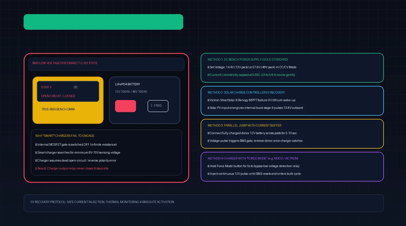
A 0V reading indicates an open-circuit BMS disconnect, not a dead battery. Because smart chargers require an existing 8V to 10V signal to engage their internal relays, you must provide an external voltage pulse to energize the BMS microprocessor and bias the MOSFET gates open. The safest recovery method is applying a current-limited 14.4V (or 57.6V) DC bench power supply capped strictly at 0.05C (2A to 5A) until cell voltages climb past 2.80V per cell.
View Smart BMS Telemetry Guide →
Anatomy of the Zero-Volt BMS Lockout State
Every commercial lithium iron phosphate battery incorporates an electronic Battery Management System. The BMS constantly monitors individual cell voltages, pack temperatures, and current flow.
Inside the negative power rail of the battery casing sits an array of parallel N-channel power MOSFETs (or a magnetic latching contactor in commercial server-rack batteries). These MOSFETs act as high-speed electronic switches.
       INSIDE THE LOCKED-OUT LiFePO4 BATTERY

  [ Cell 1: 2.21V ] ---+
  [ Cell 2: 2.19V ] ---+---> [ BMS MICROCONTROLLER ]
  [ Cell 3: 1.98V ] ---+     (Detects Cell 3 under 2.00V UVP Threshold)
  [ Cell 4: 2.24V ] ---+                 |
                                         v
                              [ GATE VOLTAGE REMOVED ]
                                         |
                                         v
   BATTERY (-) POST <========= [ DISCHARGE MOSFETS ] <========= RAW CELL PACK (-)
                              (GATE SHUT: OPEN CIRCUIT)
                               Resistance > 10 Megaohms
The Low-Voltage Disconnect Trigger
When continuous parasitic draw (such as an idle inverter, an unpowered USB socket, or months of chemical self-discharge) drains the pack, cell voltages drop.
When any single cell in the series string falls below the factory Under-Voltage Protection (UVP) limit—typically 2.00V to 2.50V per cell (8.0V to 10.0V on a 12V 4S pack, or 32.0V to 40.0V on a 48V 16S pack)—the BMS microcontroller executes an emergency shutdown:
- It pulls the gate voltage of the discharge MOSFETs to ground.
- The MOSFET channel closes, presenting an open-circuit resistance exceeding 10 Megaohms.
- The external battery terminals are completely isolated from the internal electrochemical cells.
When you touch a digital multimeter to the external terminals, you read 0.00V (or a floating phantom voltage between 0.3V and 2.5V caused by microamp leakage across the MOSFET snubber capacitors). The raw cells inside are still alive, but they are trapped behind a locked gate.
The Catch-22 of Modern Smart Battery Chargers
Why can’t you simply plug in your standard multi-stage lithium battery charger to wake the pack up?
Traditional “dumb” transformer chargers from thirty years ago output raw DC voltage continuously from their alligator clamps whether connected to a battery or not. If you touched the clamps together, they threw blinding sparks.
Modern “smart” battery chargers (such as models from NOCO, Victron, Schumacher, and CTEK) are engineered with strict safety microcontrollers governed by international consumer safety standards:
+---------------------------------------------------------------------------------+
|                        THE SMART CHARGER CATCH-22 PARADOX                       |
+---------------------------------------------------------------------------------+

  SMART CHARGER LOGIC LOOP:
  1. Clamps attached to battery posts.
  2. Internal voltmeter probes for existing terminal voltage.
  3. Safety Rule: If Voltage < 8.5V, assume reverse polarity, short circuit, or no battery.
  4. Decision: DO NOT CLOSE OUTPUT RELAY. Stay in high-impedance standby mode.

  LOCKED-OUT BMS LOGIC LOOP:
  1. Internal raw cells are depleted below 2.50V.
  2. Internal MOSFET gates are held open.
  3. Safety Rule: Keep gates open until an external charging voltage is detected.
  4. Decision: External terminals remain at 0.00V.

  RESULT: DEADLOCK
  The charger is waiting for the battery to show voltage.
  The battery is waiting for the charger to supply voltage.
  Neither device will act first.
To break this deadlock, you must introduce an external electrical source that either bypasses the charger’s sensing circuit or provides the tiny voltage pulse needed to wake the BMS.
Four Proven Methods to Revive a Locked-Out LiFePO4 Battery
Below are the four reliable methods used on our engineering test bench to unlock 12V, 24V, and 48V lithium iron phosphate batteries.
Method One: Laboratory DC Benchtop Power Supply (The Gold Standard)
A constant-current / constant-voltage (CC/CV) bench power supply is by far the safest, most controllable recovery instrument. It does not look for an existing voltage—it simply forces regulated current into any circuit connected to its leads.
       BENCH POWER SUPPLY RECOVERY SETUP

   +-----------------------+
   | DC POWER SUPPLY CC/CV |
   |  [ 14.40V ]  [ 2.00A ] |
   +---+---------------+---+
       | (+)           | (-)
       | (Red Lead)    | (Black Lead)
       v               v
   +---+---------------+---+
   | (+)               (-) |
   |  LOCKED LiFePO4 PACK  |
+-----------------------+- Configure Voltage: Set the power supply voltage limit to the nominal absorption target:
- 12V Pack (4S): Set to
14.40V. - 24V Pack (8S): Set to
28.80V. - 48V Pack (16S): Set to
57.60V.
- 12V Pack (4S): Set to
- Configure Current Limit: Turn down the current knob to restrict maximum current to 0.02C to 0.05C:
- For a 100Ah battery: Set current limit to 2.0A to 5.0A.
- For a 200Ah battery: Set current limit to 4.0A to 8.0A.
- Connect Leads: Turn the power supply output OFF. Connect the red positive clamp to the battery positive post, and the black negative clamp to the battery negative post.
- Engage Power: Switch the power supply output ON.
- Observe Behavior: The power supply display will instantly switch from CV to CC mode. The voltage reading will drop to match the raw cell pack voltage (typically around 9.0V to 10.5V on a 12V battery), and current will hold rock-steady at your setpoint (e.g., 2.0A).
- The BMS Reset Point: After 2 to 5 minutes of low-current injection, the internal cells will cross the 2.50V recovery threshold. The BMS microcontroller boots up, and the main MOSFETs snap fully open. The voltage will begin climbing smoothly toward 13.0V+.
Method Two: Solar Charge Controller 0V Lithium Wake-Up
Many modern solar charge controllers—most notably Victron SmartSolar MPPT, Renogy Rover, and EPEVER Tracer—incorporate built-in 0V lithium wake-up circuitry.
Unlike standard AC wall chargers, these solar controllers draw their operating power directly from the Solar PV Array, not the battery bank.
- Ensure Adequate Solar Input: Ensure your solar panels are in clear daylight and producing an open-circuit voltage at least 5V higher than nominal battery voltage.
- Connect Controller to Battery: Ensure the controller’s battery output terminals are wired securely to the locked-out battery posts.
- Internal Buck Converter Pulse: The solar controller detects that solar PV power is available. Recognizing that the battery terminals read zero, its internal buck converter sends a periodic low-current 13.8V DC pulse outward to the battery terminals.
- BMS Wake-up: This pulse biases the BMS gate driver circuit, unlocking the MOSFETs. Once the controller detects the true pack voltage, it enters standard bulk charging mode.
Method Three: Parallel Jump-Start from a Known Healthy Battery
If you are stranded in the field or off-grid without a benchtop power supply, you can jump-start a locked-out battery using a second, healthy battery of identical nominal voltage (e.g., jump a locked 12V LiFePO4 from a healthy 12V LiFePO4 or 12V AGM lead-acid battery).
+---------------------------------------------------------------------------------+
|                       PARALLEL JUMP WAKE-UP WITH CURRENT BUFFER                 |
+---------------------------------------------------------------------------------+

   [ HEALTHY 12V BATTERY ]                  [ LOCKED-OUT 12V BATTERY ]
  +-----------------------+                +--------------------------+
  |  (+) POS     (-) NEG  |                |  (+) POS        (-) NEG  |
  +---+------------+------+                +----+--------------+------+
      |            |                            ^              ^
      |            |   (Negative Jumper)        |              |
      |            +============================+==============+
      |                                         |
      |   (Positive Jumper with 12V Bulb Buffer)|
      +=================[ 12V 50W BULB ]========+
(Limits Inrush to ~4A)- Prepare a Current Buffer: Never connect two lithium batteries directly in parallel with heavy jumper cables without a buffer! If the locked pack’s internal cells are low and the donor pack is at 13.5V, several hundred Amps of instantaneous inrush current can arc across terminals and weld contacts.
- Insert an Inrush Limiter: Wire an ordinary 12V 50W automotive incandescent headlight bulb or a 1-ohm 50W aluminum power resistor in series on the positive jumper cable.
- Execute the Jump:
- Clamp the black jumper cable between Donor Battery (-) and Locked Battery (-).
- Clamp the red jumper cable between Donor Battery (+) and Locked Battery (+) through the series bulb.
- BMS Activation: The donor battery supplies a steady 12V signal through the bulb filament, pulling the locked battery’s terminals above the UVP threshold. The bulb may glow dimly for several seconds.
- Engage Smart Charger: While the parallel jumper is still connected, attach your standard smart battery charger to the locked battery’s posts.
- Remove Donor: The smart charger now senses 12V from the donor battery and closes its internal relay. The moment the smart charger begins pumping current, disconnect the jumper cables and donor battery.
Method Four: Dedicated Smart Charger “Force Mode”
Select premium consumer chargers—such as the NOCO Genius series (Force Mode) or Victron Blue Smart IP65 (Power Supply / Recondition Mode)—include a manual override button specifically designed to bypass low-voltage detection.
- Connect the charger clamps to the battery posts (Red to Positive, Black to Negative).
- Press and hold the Force Mode button (or Mode button) for 5 continuous seconds.
- The charger disables its internal voltage sensing relay and forces a continuous, low-amperage 12V or 24V DC charging current onto the output clamps.
- Once the battery terminals rise above the minimum detection threshold (typically after 5 to 10 minutes), the charger automatically returns to its standard automated lithium charge profile.
Critical 10-Minute Recovery Window and Thermal Protocol
Reviving an over-discharged lithium battery is not without risk. While lithium iron phosphate is fundamentally safer than cobalt-based lithium chemistries, severe over-discharge introduces chemical stress.
When a cell drops below 1.50V per cell, the copper anode current collector begins to dissolve into the liquid electrolyte. If an over-discharged battery is subjected to high charging currents (e.g., hitting it with a 50A alternator or 100A inverter charger), the dissolved copper precipitates out as microscopic metallic copper dendrites. These dendrites can pierce the microporous polymer separator, causing internal short circuits and thermal runaway.
+---------------------------------------------------------------------------------+
|                       THE 10-MINUTE REVIVAL SAFETY WINDOW                       |
+---------------------------------------------------------------------------------+

  MINUTE 0 to 10: TRICKLE CHARGE ONLY
  - Current Limit: Strictly 0.02C to 0.05C (e.g., 2A to 5A on a 100Ah pack).
  - Target: Gently bring cell voltages from ~2.0V up to 2.80V per cell.
  - Temperature Check: Inspect casing with an infrared thermometer every 2 minutes.

  TEMPERATURE PASS/FAIL CRITERIA:
  - Normal: Casing remains at ambient temperature (20°C to 25°C / 68°F to 77°F).
  - HAZARD: Any localized spot warming by >5°C (>9°F) indicates an internal cell
            short circuit. DISCONNECT POWER IMMEDIATELY AND RETIRE BATTERY.

  MINUTE 10+: NORMAL CHARGING
  - Once all cells cross 2.80V (11.2V on 12V pack, 44.8V on 48V pack), normal
    0.2C to 0.5C charging may safely resume.
Sensory Inspection Checklist
During the initial 10-minute revival phase, maintain continuous physical observation:
- The Sniff Test: Sniff near the battery vents or seams. Any sweet, solvent-like, or chemical odor indicates that a cell safety valve has ruptured and electrolyte is venting. If smelled, abort charging immediately.
- Casing Swelling: Visually inspect the prismatic cells or outer plastic case. Any bulging or pillowing of the casing walls indicates internal gas generation from degraded electrolyte.
- Cell Voltage Delta: If your battery features Bluetooth BMS telemetry (e.g., JBD, Daly, Overkill, Epoch), monitor the real-time cell voltages on your smartphone. All series cells should rise together within 0.050V (50mV) of each other. If one cell remains stuck at 1.8V while others jump to 3.2V, that low cell has suffered internal shorting.
Assessing Permanent Damage vs Safe Return to Service
Once your battery has been successfully unlocked, brought through a full absorption cycle (14.4V / 57.6V), and allowed to rest for 4 hours, execute these three diagnostic tests before reinstalling it into your whole-home power wall or RV:
| Diagnostic Assessment | Testing Protocol | Passing Benchmark | Failing Benchmark (Retire Battery) |
|---|---|---|---|
| Internal AC Resistance | Test across terminals with a 1kHz Kelvin 4-wire tester (e.g. YR1035+) | Under 5.0 m (12V 100Ah pack) or under 0.8 m per raw prismatic cell | Resistance doubled compared to factory spec (over 10.0 m), indicating anode degradation |
| Open-Circuit Voltage Retention | Measure terminal voltage after resting 24 hours with zero loads attached | Pack voltage holds steady at 13.30V to 13.40V (3.33V/cell) | Voltage drops below 13.00V within 24 hours, indicating severe self-discharge |
| Full Capacity Discharge Test | Discharge pack at 0.2C (20A on 100Ah) through an electronic load tester down to 10.5V | Delivers >90% of rated factory capacity | Delivers under 80% of rated capacity, or single cell collapses rapidly under load |
If the battery passes all three benchmarks—maintaining low internal resistance, holding voltage across 24 hours of rest, and delivering over 90% of its rated Amp-hours—it is chemically sound and safe to return to full cycle duty.
Frequently Asked Questions
Can I jump-start a 12V LiFePO4 battery using my car’s alternator?
You can use a running vehicle’s 12V lead-acid battery to provide the momentary 12V pulse needed to trigger the BMS, but you should disconnect the jumper cables within 30 seconds of the BMS unlocking. Never leave a deeply discharged LiFePO4 battery connected directly to a car alternator with standard heavy jumper cables; the depleted lithium pack will pull 80A to 120A continuous from the alternator, which can overheat and fry the vehicle’s alternator windings at idle.
How long can a LiFePO4 battery sit in 0V lockout before permanent damage occurs?
If the BMS disconnected when the cells were at 2.50V, the battery can safely sit in lockout for 1 to 3 months because self-discharge is very low. However, if parasitic loads slowly drained the raw cells down to between 1.50V and 2.00V, irreversible copper dissolution begins within 1 to 2 weeks. If raw cells sit below 1.00V for more than 48 hours, permanent chemical destruction has occurred, and the battery should not be revived.
Does an emergency BMS 0V reset void my manufacturer warranty?
No. Performing a standard 0V recovery using external voltage injection is a standard maintenance procedure approved by manufacturers like Victron, Battle Born, EG4, and SOK. However, opening the physical battery enclosure, cutting seals, or physically soldering wires across the BMS MOSFET pads to force a mechanical bypass will void your factory warranty.
How do I prevent my battery from ever locking out again?
Configure your solar inverter and DC load disconnects with a conservative Low-Voltage Disconnect (LVD) threshold that engages well before the BMS is forced to shut down. Setting your inverter LVD to 12.0V (or 48.0V) ensures household loads disconnect while the battery still has 15% reserve capacity, leaving plenty of energy to keep the BMS microcontroller powered for months of storage.