Growatt off-grid and all-in-one hybrid inverters—most notably the SPF 3000TL LVM-48P, SPF 5000ES, and SPF 12000T DVM—are among the most popular power conversion units installed in off-grid cabins, workshops, and DIY solar microgrids. They pack a high-voltage MPPT solar charge controller, a pure sine wave DC-to-AC inverter, and an AC battery charger into a single cost-effective chassis.
However, when an electrical anomaly occurs, the unit’s red fault LED illuminates, an ear-splitting alarm buzzer sounds, and a two-digit cryptic error code flashes on the LCD screen: Error 04, Error 08, Error 51, or Error 58.
Too often, DIY builders assume their inverter is permanently destroyed or engage in fruitless component swapping. In reality, over 85% of Growatt error codes are caused by incorrect menu configuration, cold-weather solar array voltage spikes, or high-resistance battery cable crimps.
In this bench-tested diagnostic guide, we dissect the electrical physics behind Growatt’s most common error codes, provide step-by-step multimeter diagnostic procedures, explain exact menu parameter adjustments, and outline firmware recovery protocols.
Before assuming internal hardware failure, isolate the unit: disconnect AC loads and PV DC input, leaving only the 48V battery connected. Error 04 is resolved by calibrating Setting 21 to 44.8V and Setting 12 to 48.0V in User (US2) battery mode. Error 08 is prevented by recalculating winter cold-temperature solar string Voc below 425V DC. Error 51 requires checking for downstream AC neutral-ground bonding loops or adding a soft starter for compressor loads.
Check Battery Cable Voltage Drop Calculator →
Error 04: Battery Voltage Too Low
Error 04 is the single most common fault code encountered on Growatt off-grid systems. It signifies that the DC voltage measured at the inverter’s battery input terminals has fallen below the Low DC Cut-off Voltage threshold defined in the system firmware.
The Hidden Root Causes
- BMS Low-Voltage Disconnect: A single out-of-balance cell inside your 16S LiFePO4 battery hits 2.50V, prompting the internal BMS to trip open. The inverter terminal voltage drops to zero instantly, triggering Error 04.
- Severe Cable Voltage Drop (): Using undersized 4 AWG cables on a 3,000W load causes a 3V to 4V drop between the battery terminals and the inverter lugs. While the battery sits at 48V, the inverter senses under 44V.
- Mismatched Lead-Acid Presets: Leaving Setting 05 set to AGM or Lead-Acid forces aggressive 42V cutoffs that confuse modern lithium batteries.
The Multi-Step Fix
- 1. Multimeter Terminal Audit: Measure voltage directly across the Growatt DC lugs while under load. If the reading is more than 0.5V lower than the battery BMS reading, your cables are undersized or connections are loose.
- 2. Configure User Battery Mode (US2): Enter the Growatt LCD menu, navigate to Setting 05, and change from “LI” or “AGM” to “USE” (or “US2”).
- 3. Adjust Setting 21: Set Low DC Cut-off Voltage (Setting 21) to 44.8V (2.80V per cell for 16S LFP). This prevents deep-discharge BMS lockouts.
Error 08: DC Bus Voltage Exceeds Upper Limit
Error 08 is a critical high-voltage protection trip. Inside the Growatt inverter, a high-frequency DC-DC boost stage elevates 48V battery and solar voltage onto a high-voltage Internal DC Bus (typically regulated between 360V and 460V DC) before the H-bridge switches it into 120V/240V AC.
If the voltage across the main electrolytic bus capacitors exceeds 500V DC, the microcontroller trips Error 08 within microseconds to prevent the capacitors from exploding.
⚡ Physics of DC Bus Overvoltage ()
On a Growatt SPF 5000ES or SPF 3000TL LVM-48P with a 450V or 500V max PV input, stringing nine or ten 400W–450W panels produces roughly 440V Voc at standard . But on a freezing () winter morning, panel voltage rises by up to 14%:
The instant the MPPT tries to sweep the I-V curve, the raw open-circuit voltage overcharges the internal bus, instantly triggering Error 08.
When a high-power inductive load (such as a 3HP well pump or 15A table saw) suddenly shuts off, the collapsing magnetic field in the motor coils dumps inductive energy back into the inverter’s output filter stage. If the bus capacitors cannot absorb the back-EMF surge fast enough, bus voltage surges past 500V, tripping Error 08.
Bench Solution for Error 08
- Calculate Conservative Voc: Keep your series string maximum open-circuit voltage at least 15% below the Growatt rated PV limit (e.g., maximum 380V Voc for a 450V rated MPPT). Use our Cold-Temperature Voc Calculator to verify winter temperature coefficients.
- Firmware Soft-Start Calibration: In early SPF 5000ES firmware versions, aggressive MPPT algorithm tracking caused overshoot oscillations. Updating to DSP firmware version 040.05 or higher smooths MPPT bus voltage regulation under variable cloud cover.
Error 51: Inverter Overcurrent Hardware Trip
Error 51 indicates that the instantaneous current flowing through the inverter’s power transistors (MOSFETs or IGBTs) exceeded the factory hardware trip threshold—typically 200% to 250% of nominal rating for more than 10 to 20 milliseconds.
Root Cause Analysis
- Motor Inrush Current (Locked Rotor Amps): When central air conditioners, refrigerators, or air compressors start across-the-line without a soft starter, starting inrush current reaches 5 to 7 times running amps. A 2,500W compressor can pull 15,000 Watts instantaneously, triggering Error 51.
- Downstream Neutral-Ground Loop Fault: If your AC subpanel has a bonding screw installed while the Growatt also has an internal bonding relay active, parallel neutral return currents circulate through the chassis ground wire, saturating the inverter’s Hall-effect current sensors.
- Blown Output MOSFETs: If Error 51 triggers immediately upon flipping the power switch with zero AC loads connected, one or more MOSFETs in the H-bridge inversion bridge have suffered catastrophic gate punch-through (shorted drain-to-source).
To determine whether Error 51 is an external wiring fault or internal component failure:
- Completely Power Down: Disconnect AC input, turn off PV breakers, switch off the battery disconnect, and wait 10 full minutes for internal bus capacitors to discharge safely below 10V DC.
- Disconnect AC Output Wiring: Remove the Line (L), Neutral (N), and Ground (G) wires from the AC Output terminal block.
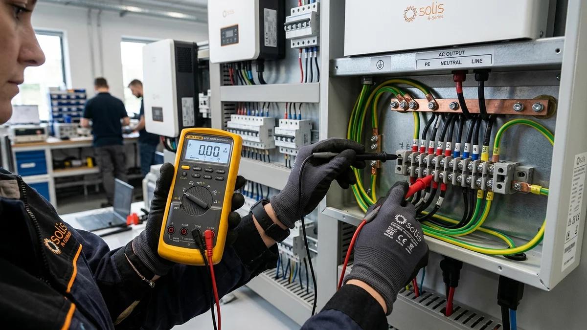
- Diode Check Mode: Set your digital multimeter to Diode Test Mode (. Probe between the AC Line terminal and DC Battery Positive (+) lug, then between Line and DC Negative (-) lug.
- Reading Interpretation: A healthy H-bridge diode will read between 0.400V and 0.550V in forward bias and O.L (Open Loop) in reverse bias. A reading of 0.000V (continuous beep) indicates a shorted MOSFET requiring board-level repair or mainboard replacement.
Error 58: Inverter Output Voltage Too Low
Error 58 triggers when the inverter senses that its output AC voltage has collapsed below 90V AC (on 120V models) or 180V AC (on 230V models) while the inversion circuit is commanding full pulse-width modulation (PWM).
Diagnostic Checklist for Error 58
- High-Resistance DC Lug Crimps: Under a 2,000W load, pulling 45 Amps through a loose or improperly crimped battery cable lug generates massive resistive voltage drop. The DC input voltage collapses at the motherboard level while the battery terminal reads normal. Inspect all battery cables with a thermal camera or infrared thermometer; any terminal running hotter than () must be re-crimped and torqued to 9.5 Nm (84 in-lbs).
- Defective Inverter Output Relay: Growatt inverters use electromechanical relays to switch between grid bypass and off-grid inverter mode. Pitted or carbonized relay contacts introduce severe internal resistance, causing output voltage to collapse under moderate load.
- Setting 01 Parameter Conflict: If Output Source Priority (Setting 01) is set to SOL (Solar First) or SBU (Solar-Battery-Utility), and the battery reaches low cutoff during an inductive motor start, the inverter attempts to transfer back to utility. If utility AC is disconnected or out of frequency tolerance, Error 58 trips.
Comprehensive Growatt Menu Parameter Sizing Guide
To prevent recurring nuisance error codes on 48V LiFePO4 battery banks (such as EVE 280Ah/314Ah prismatic cells or server rack batteries), configure the following menu parameters:
| Menu Program | Parameter Description | Factory Default | Recommended Setting (16S LiFePO4) | Why It Matters |
|---|---|---|---|---|
| Program 01 | Output Source Priority | SOL / UTI | SBU (Solar → Battery → Utility) | Maximizes self-consumption without utility cycling |
| Program 05 | Battery Chemistry Type | AGM | USE (User Defined) or US2 | Bypasses flawed lead-acid voltage algorithms |
| Program 12 | Back-to-Utility Voltage | 46.0V DC | 48.0V DC (3.00V / cell) | Transfers to grid before BMS trips on low cell voltage |
| Program 13 | Back-to-Battery Voltage | 54.0V DC | 52.0V DC (3.25V / cell) | Re-engages off-grid mode once battery has substantial reserve |
| Program 19 | Bulk / Constant Charge Voltage | 56.4V DC | 56.0V DC (3.50V / cell) | Eliminates high-voltage BMS cell cutoff overshoots |
| Program 20 | Float Charging Voltage | 54.0V DC | 54.0V DC (3.375V / cell) | Maintains 100% capacity without continuous thermal degradation |
| Program 21 | Low DC Cut-off Voltage | 42.0V DC | 44.8V DC (2.80V / cell) | Completely eliminates Error 04 nuisance trips |
Firmware Flashing & Recovery Protocol
If your Growatt inverter exhibits persistent unexplainable Error 08, Error 58, or communication lockups despite verified hardware wiring, flashing the latest firmware often resolves firmware-level DSP timing bugs:
Required Equipment
- USB-to-RS485 Communication Cable (FTDI chipset recommended).
- Growatt ShineBus Desktop Software (Windows 10/11).
- Verified Hex/Bin Firmware Package matching your exact model and CPU architecture (ARM vs DSP).
[!CAUTION] Flashing the incorrect firmware revision (e.g., flashing European SPF 5000ES firmware onto an American SPF 3000TL LVM-48P) will permanently brick the main control board. Always confirm the current DSP and MCU firmware version displayed on LCD screens 26 and 27 before initiating a flash. Never disconnect DC power during a firmware write cycle!
Frequently Asked Questions (FAQ)
Can I clear a Growatt error code by power cycling?
Yes, for transient faults (like Error 04 caused by a temporary heavy load or Error 08 caused by an inductive load drop), turning the bottom power rocker switch OFF, waiting 30 seconds until the screen goes blank, and turning it back ON will clear the code. However, if the underlying electrical condition persists, the code will re-trigger within seconds.
Why does my Growatt inverter beep continuously with Error 04?
The loud, persistent alarm buzzer is the mandatory low-voltage warning mandated by electrical safety standards. You can temporarily mute the audible alarm by navigating to Program 18 (Alarm Control) in the menu and changing the setting from BON (Buzzer On) to BOF (Buzzer Off). Note that this disables the sound but does not clear the underlying fault.
Is Error 51 covered under Growatt warranty?
If Error 51 is caused by internal component failure (such as a factory-defective MOSFET or weak solder joint) within the standard warranty period, Growatt or your authorized distributor (such as Signature Solar) will replace the mainboard. However, if the failure was caused by external lightning surge, reverse battery polarity, or running central AC compressors without surge protection, the warranty claim will be denied.
Final Troubleshooting Verdict
Growatt off-grid inverters are workhorse units, but their sensitive onboard microcontrollers will not tolerate sloppy wiring, undersized battery cables, or reckless solar string voltage sizing.
- For Error 04: Switch Setting 05 to User (US2), set Setting 21 to 44.8V, and verify your DC battery cables are sized for less than 1% voltage drop.
- For Error 08: Calculate your solar string Voc at winter freezing temperatures and ensure it stays comfortably below 425V DC.
- For Error 51: Disconnect all AC loads and inspect H-bridge MOSFETs with a digital multimeter before assuming downstream failure.
By systematically applying these bench-tested diagnostic procedures, you can demystify Growatt error codes, protect your energy storage equipment, and keep your off-grid solar system operating with 100% dependability.