Commercial solar sales companies frequently treat photovoltaic design as an arcane, proprietary mystery. In reality, residential and off-grid solar systems obey well-established laws of physics and electrical engineering.
You do not need an engineering degree or an expensive $500 certified contractor course to design, size, and safely install a high-performance solar power setup.
This Free Solar Power Course is designed as a structured, university-grade curriculum. Whether you are building a portable emergency power station, outfitting an overland camper van, or wiring an off-grid homestead with server rack batteries and hybrid inverters, this step-by-step syllabus covers the exact electrical math, hardware selection criteria, and National Electrical Code (NEC) safety practices required to build with complete confidence.
Every solar system—from a $300 camping kit to a $30,000 whole-home installation—consists of four core stages: Generation (PV Panels), Regulation (MPPT Controller), Storage (LiFePO4 Battery Bank), and Conversion (Pure Sine Wave Inverter). By mastering the core circuit math (Volts × Amps = Watts) and sizing for peak motor surge and inverter tare loss, you can build a reliable, code-compliant off-grid system without paying for expensive sales consulting.
Launch Interactive Sizing Calculator →
Course Curriculum: The Six Core Solar Disciplines
Electrical Fundamentals
Master Volts, Amps, Watts, Ohms, and the hydraulic circuit analogy that governs all DC and AC electricity.
PV Panel Physics
Understand monocrystalline cell silicon, STC ratings, temperature derating coefficients, and shading bypass diodes.
Array Sizing & String Math
Series vs parallel wiring, calculating open-circuit voltage () cold spikes, and matching MPPT controller limits.
Battery Storage & BMS
LiFePO4 prismatic cell chemistry, 80% Depth of Discharge, C-rates, cell balancing, and cold charging cutoffs.
Inverters & Power Delivery
Pure sine wave generation, Total Harmonic Distortion (THD), motor locked rotor amps (LRA), and inverter tare loss.
Fusing, Wiring & Code
AWG wire gauge selection, 3% voltage drop limits, Class T fast-acting fusing, and NEC Article 690 grounding.
Electrical Fundamentals for Solar Systems
Before touching a single wire or solar panel, you must be completely fluent in the four fundamental electrical parameters:
The Hydraulic Analogy of Electricity
To visualize electrical flow, imagine water flowing through a closed plumbing pipe system:
- Voltage (, measured in Volts): Water pressure. It represents the potential electrical force pushing electrons through a circuit. A 48V battery has four times more electrical pressure than a 12V battery.
- Current (, measured in Amperes / Amps): Water flow rate. It represents the actual volume of electrons passing a given point per second.
- Resistance (, measured in Ohms ): The pipe diameter restriction. Friction that opposes electrical current flow, converting some energy into wasted heat.
- Power (, measured in Watts): The total work done by the water turning a waterwheel.
The Two Non-Negotiable Circuit Equations
All solar engineering calculations trace back to two primary formulas:
From the Power Formula, we derive the relationship that explains why higher-voltage systems are vastly superior for high-power applications:
The High-Voltage Efficiency Lesson: Suppose you want to run a 2,400W kitchen appliance from a battery bank:
- On a 12V battery bank: . Pushing 200 Amps requires massive 4/0 AWG copper welding cable (as thick as a thumb) to prevent dangerous overheating.
- On a 48V battery bank: . Pushing 50 Amps only requires standard 6 AWG copper wire, cutting copper weight and cost by over 70% while drastically reducing heat loss.
Photovoltaic Panel Physics and Real-World Derating
Solar panels do not operate like AC wall outlets; their output varies dynamically depending on sunlight intensity (irradiance), ambient temperature, and cell physics.
Understanding Nameplate Specs (STC vs Real World)
Every solar panel displays a sticker on its backplate showing ratings measured under laboratory Standard Test Conditions (STC: 1,000 W/m² sunlight, 25°C / 77°F cell temperature). In the field, real output is lower due to environmental variables.
Voltage measured across terminals with zero load connected. Critical for MPPT safety limits.
Voltage delivered when the panel is operating at peak efficiency under load (typically ~80% of ).
Amperage when positive and negative terminals are shorted together. Governs wire and fuse sizing.
The Solar Thermal Derating Factor
Most newcomers assume solar panels produce the most electricity on hot 95°F (35°C) summer afternoons. In fact, silicon solar cells lose efficiency as they heat up.
A panel sitting in direct summer sunlight easily reaches cell temperatures of 65°C (149°F)—a 40°C rise over STC test conditions.
With a typical temperature coefficient of :
When combined with atmospheric humidity and reflection angles, expect real-world peak output to be 75% to 80% of rated nameplate wattage. A 400W panel will realistically generate between 300W and 320W in full midday sun.
Solar Array Wiring: Series vs Parallel Circuits
When combining multiple solar panels to charge a power station or battery bank, how you wire them dictates whether voltage or amperage increases:
Multiplies Voltage, Keeps Amps Constant
Connecting panel #1 positive to panel #2 negative adds their voltages together while total current remains that of a single panel.
- Allows thinner wire and longer cable runs with minimal voltage drop.
- Starts MPPT charging earlier at sunrise due to higher string voltage.
- Vulnerable to shading: partial shade on one panel throttles the entire string.
Multiplies Amps, Keeps Voltage Constant
Connecting all positive leads together and all negative leads together sums the total amperage while system voltage remains unchanged.
- Excellent shade tolerance: shaded panels do not drag down unshaded parallel strings.
- Keeps array voltage low, ideal for small power stations with 30V or 60V MPPT limits.
- Requires thicker copper wire and heavier branch fuses to carry high amperage.
[!WARNING] Cold Weather Voc Warning: Never design a series array right up to your charge controller’s maximum voltage limit. When temperature drops, panel voltage spikes. If an MPPT is rated for 150V, an array with 140V at 25°C will exceed 155V on a frosty 15°F (-9°C) morning, causing permanent hardware destruction. Always maintain a 15% to 20% voltage safety margin.
Battery Storage Engineering: LiFePO4 Chemistry & BMS Protection
In an off-grid system, the battery bank is typically your largest financial investment. Understanding cell chemistry and battery management systems ensures your investment lasts 10 to 15 years rather than failing prematurely.
Why LiFePO4 (LFP) Is the Gold Standard
Lithium Iron Phosphate () has largely replaced traditional Lithium Nickel Manganese Cobalt (NMC) and flooded lead-acid batteries in solar energy storage:
- Cycle Life: Quality prismatic LiFePO4 cells deliver 3,500 to 5,000 full discharge cycles to 80% original capacity. That equates to over 10 years of daily cycling. Lead-acid AGM batteries fail after 300 to 500 cycles.
- Usable Depth of Discharge (DoD): LiFePO4 can be safely discharged to 80%–90% DoD without damage. In contrast, lead-acid batteries must never be discharged below 50% DoD, meaning a 100Ah lead-acid battery only provides 50Ah of usable power.
- Flat Voltage Discharge Curve: A 48V LiFePO4 battery maintains 51V to 53V throughout 85% of its discharge cycle, providing stable, constant voltage to inverters without causing low-voltage motor trip-outs.
The Critical Role of the Battery Management System (BMS)
Raw lithium cells cannot be charged directly; they require a computerized Battery Management System (BMS) to prevent catastrophic failure:
- Over-Voltage & Under-Voltage Cutoff: Prevents individual cells from exceeding 3.65V (overcharge) or dropping below 2.50V (over-discharge).
- Active Cell Balancing: Micro-transfers charge between cells to ensure all 16 cells in a 48V pack reach full charge simultaneously.
- Low-Temperature Charge Disconnect: Never charge lithium batteries below freezing (0°C / 32°F). Charging cold lithium causes metallic lithium plating on the anode, resulting in internal short circuits and permanent capacity destruction. Modern smart BMS units include temperature probes that automatically disable charging while permitting discharge down to -20°C (-4°F).
Inverter Sizing & Power Delivery: Continuous vs Surge Watts
An inverter’s job is converting DC battery voltage into clean 120V or 240V AC 60Hz utility power. To pick the right inverter, you must evaluate three technical benchmarks:
Continuous Running Watts vs Motor Surge (LRA)
Resistive loads (heaters, incandescent lamps, toasters) draw a constant wattage from startup to shutdown. However, inductive motor loads (refrigerator compressors, well pumps, air conditioners, circular saws) demand a massive initial current spike—known as Locked Rotor Amps (LRA)—lasting 100ms to 2 seconds to establish the motor’s magnetic field.
- A 1/2 HP submersible well pump might run at 900W, but requires 3,200W to 4,000W of instantaneous surge power to kick on.
- Always ensure your inverter’s surge wattage rating (usually 2x continuous rating) comfortably exceeds the highest inrush spike of your largest motor appliance.
Pure Sine Wave vs Modified Sine Wave
Never compromise on pure sine wave output:
- Pure Sine Wave: Generates a silky smooth sinusoidal waveform with less than 3% Total Harmonic Distortion (THD), identical to or cleaner than utility grid power. All sensitive electronics, CPAP machines, audio equipment, and brushless motors run efficiently and quietly.
- Modified Sine Wave: Generates a crude, stepped square-wave. Inductive motors run 20% to 30% hotter, emit an annoying buzz, and can suffer premature insulation breakdown.
Inverter Tare Loss (Idle Power Draw)
As highlighted in our Inverter Tare Loss Analysis, inverters consume energy simply being powered ON. A 3,000W inverter left idling 24 hours a day consumes between 25W and 45W continuously, burning 600Wh to 1,000Wh of battery energy daily even if zero appliances are plugged in!
Top Recommended Equipment for Every Solar Learner
Whether you prefer a pre-engineered portable power station or a modular rack-mount component system, these four field-tested units provide unmatched engineering reliability:
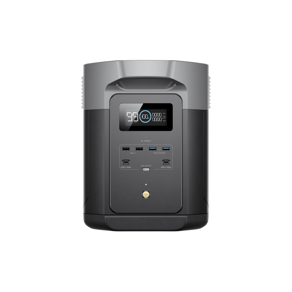
1. EcoFlow DELTA 2 Max
The ideal educational and practical solar powerhouse. Its dual independent MPPT charge controllers (500W each / 1,000W combined) allow you to experiment with two separate solar arrays simultaneously (e.g. comparing series vs parallel strings or east vs west facing panels). Equipped with 2,048Wh of long-life LiFePO4 cells and 2,400W continuous pure sine output.
Check Price & Deals →

2. Anker SOLIX C1000 Gen 2
If you want to start small without sacrificing professional features, the C1000 Gen 2 packs 1,056Wh of LiFePO4 storage and an 1,800W pure sine wave inverter into an ultra-portable frame. Its 600W MPPT solar input accepts up to 60V, making it seamless to connect two or three 200W panels in series for high-speed field charging.
Check Price & Deals →
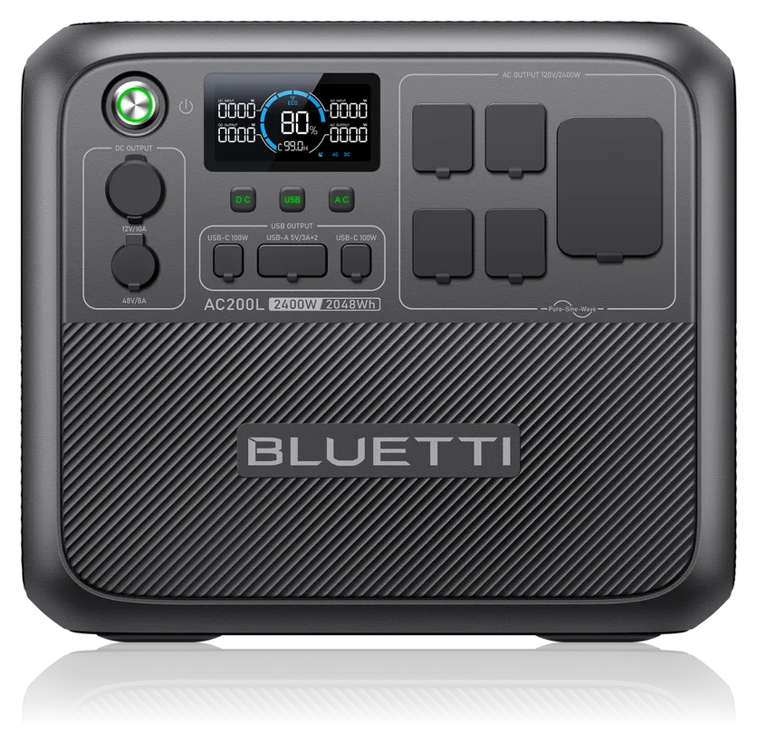
3. Bluetti AC200L
The ultimate power station for learners wanting to interface with standard high-voltage residential solar panels. Its industrial-grade MPPT accepts up to 145V and 1,200W of solar input, allowing you to run three 400W rooftop panels in series without clipping. Features a native 48V DC expansion port and 2,400W continuous output.
Check Price & Deals →

4. Anker SOLIX F3800
For students ready to master whole-house electrical integration. The F3800 outputs native 120V/240V split-phase power with an onboard NEMA 14-50 receptacle, allowing direct plug-in to home generator inlet boxes. Its 3.84kWh base capacity qualifies for the 30% federal clean energy tax credit (Section 25D) on its own.
Check Price & Deals →
Costly DIY Solar Mistakes to Avoid
Even skilled DIYers occasionally make simple calculation oversights. Here are the four most common solar installation mistakes and how to prevent them:
Mistake: Undersizing Wire Gauge and Violating the 3% Voltage Drop Rule
National Electrical Code (NEC Article 210.19) recommends that branch conductors have no more than a 3% voltage drop at full rated load. Using undersized 14 AWG wire on a long 40-foot 12V DC cable run can cause a 10% voltage drop—generating intense heat in the cable and depriving your charge controller of useful charging wattage. Always calculate wire gauge using an engineering conductor chart based on one-way distance and maximum amperage.
Mistake: Mixing Mismatched Panels in the Same Series String
If you place a 100W panel (5 Amps ) in series with a 400W panel (10 Amps ), the entire circuit is bottlenecked to the lowest current rating in the string:
The 400W panel will be choked down to producing only 200W, wasting half its capacity. Always ensure all panels in a series string share identical or nearly identical current ratings.
Mistake: Omitting Fast-Acting Class T Fuses on Lithium Battery Banks
LiFePO4 battery banks have extraordinarily low internal resistance. In a dead short-circuit event, a 48V 100Ah battery bank can deliver over 10,000 Amps of short-circuit current in milliseconds—instantly vaporizing ordinary automotive fuses and causing severe arc-flash explosions. Always install a UL-listed Class T fuse (rated for 20,000A to 50,000A AIC interrupt capacity) immediately at the positive battery terminal.
Mistake: Leaving Inverter Idle Draw Unchecked
Leaving an AC inverter powered ON 24 hours a day to charge a phone or keep a router running can burn up to 1,000Wh daily in tare loss. Whenever possible, run low-voltage loads (LED lights, routers, USB gadgets) directly from the 12V DC or 48V DC busbars with native DC-DC step-down converters rather than using the AC inverter.
Frequently Asked Questions (FAQ)
Can I legally install a solar and battery system myself without a licensed electrician?
Yes, for portable solar generators and standalone off-grid systems, zero permits or licensed electrical work are required. However, if you plan to hardwire an inverter into your home’s main distribution panel via an interlock kit, transfer switch, or grid-tie net-metering connection, local building codes and the National Electrical Code (NEC) require pulling an electrical permit and hiring a licensed electrician or passing a homeowner electrical inspection.
What is the difference between grid-tied, off-grid, and hybrid solar systems?
- Grid-Tied (Net-Metered): Connects directly to the utility grid without batteries. It sends excess solar to the utility company for bill credits, but shuts down instantly during blackouts for utility lineworker safety.
- Off-Grid: Completely detached from the utility grid. Requires substantial battery storage and backup generators to ensure uninterrupted power during cloudy winter weeks.
- Hybrid (Grid-Interactive with Storage): The modern gold standard. Remains connected to the utility grid to sell excess power, but automatically islands itself into an off-grid battery microgrid during power outages.
How do I know whether my panels should be wired in series or parallel?
Check your charge controller’s specifications:
- If your controller has a high maximum voltage limit (e.g. 100V to 150V ) and you have a long wire run from your roof or yard, wire in series to keep amperage low and minimize wire resistance losses.
- If your charge controller has a low voltage limit (e.g. 30V or 60V) or your panels experience partial tree shading during parts of the day, wire in parallel (or series-parallel strings) to maintain charging voltage without exceeding controller safety limits.
Does a solar system still produce power on cloudy or rainy days?
Yes, but at reduced efficiency. Photovoltaic cells respond to diffuse ambient light as well as direct sunlight. On heavily overcast or rainy days, expect solar panels to produce 10% to 25% of their rated capacity. Designing for winter or cloudy weather requires sizing your battery bank for 2 to 3 days of autonomy (energy reserve).
