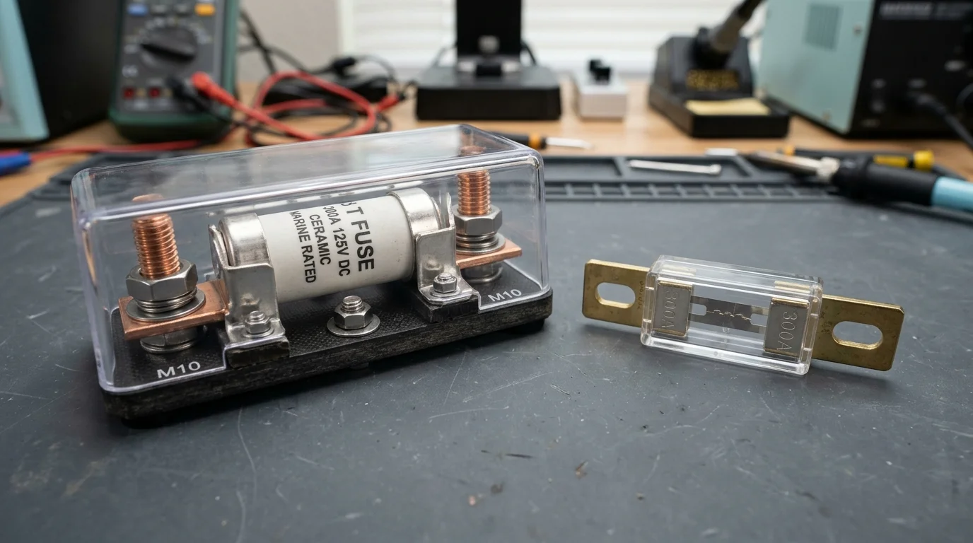
In the era of traditional lead-acid battery banks, the humble ANL fuse was the undisputed champion of DC overcurrent protection. With internal cell resistances hovering between 10 and 30 milliohms, a dead short on a 48V flooded lead-acid bank rarely pushed fault currents beyond 2,000 to 3,000 amperes—well within the breaking capability of an inexpensive ANL fuse.
The rapid rise of modern lithium iron phosphate (LiFePO4) energy storage has completely invalidated those legacy assumptions.
Large-format prismatic lithium cells—such as EVE 280Ah or 314Ah cells—exhibit ultra-low internal AC impedance (). When connected in a 16S 48V configuration, a bolted short circuit does not simply blow an ANL fuse; it overwhelms its physical interrupting threshold. The resulting electrical arc can transform the fuse into a 4,000°F plasma blowtorch, destroying switchgear and initiating structural fires.
For any lithium battery bank exceeding 100Ah, a Class T fuse is not a luxury upgrade—it is a non-negotiable life-safety requirement.
In this electrical engineering guide, we examine the physics of prospective short-circuit fault currents, compare interrupting ratings (AIC), demonstrate why ANL fuses fail explosively under lithium dead shorts, and provide precise sizing formulas for modern hybrid inverters.
Never install an ANL fuse as primary overcurrent protection on a lithium battery bank. A 48V 280Ah LiFePO4 bank can deliver over 15,000A to 25,000A of instantaneous short-circuit current, while standard ANL fuses are only rated to interrupt 2,700A to 6,000A. Exceeding this rating causes continuous sustained arcing. Only Class T fuses (rated at 20,000A+ DC AIC) can safely extinguish lithium short-circuit arcs.
Check Class T Fuse Blocks →
The Low-Impedance Reality of LiFePO4 Batteries
To understand why fuses fail, you must first calculate the Prospective Fault Current available from modern lithium energy storage.
Unlike lead-acid or AGM batteries that suffer massive internal voltage sag during high-current discharge, prismatic LiFePO4 cells are engineered for exceptionally high conductivity. A standard Grade A 3.2V 280Ah cell features an internal impedance () of roughly 0.18 to 0.25 milliohms ().
When 16 of these cells are wired in series to create a nominal 51.2V pack, the total internal chemical resistance of the cells is:
If you factor in internal copper busbars, terminal posts, and 6 feet of 4/0 AWG fine-stranded battery cable (), total system loop resistance () under a dead bolted short is barely 0.0045 ohms.
Applying Ohm’s Law () reveals the true magnitude of a dead short:
If a homeowner parallels two or three server rack batteries (e.g. two Seplos Mason 280Ah packs or EG4 LifePower4 stacks), parallel branch resistance drops by half, and prospective fault currents routinely soar past 22,000 to 35,000 Amperes.
Interrupt Ratings Compared: Class T vs ANL vs MRBF
A fuse is not merely a piece of metal designed to melt at its continuous amp rating (e.g. 200A or 300A). The most critical safety parameter of any fuse is its Ampere Interrupting Capacity (AIC)—also referred to as the Interrupt Rating (IR).
The AIC represents the maximum fault current that the fuse can physically interrupt and clear without rupturing its casing, maintaining an internal electric arc, or bursting into flames.
| Fuse Category / Standard | Typical Continuous Amperage | DC Voltage Rating | DC Interrupt Rating (AIC) | Internal Arc-Quenching Medium |
|---|---|---|---|---|
| Class T (JJN / JLLN) | 110A – 800A | 125V – 160V DC | 20,000A @ 125V DC (100kA AC) | Granular Quartz Silica Sand |
| ANL Standard Fuse | 35A – 750A | 32V – 80V DC | 2,000A – 6,000A @ 32V (~2.7kA @ 48V) | None (Open Air inside Mica/Plastic) |
| MRBF (Marine Battery Fuse) | 30A – 300A | 58V DC | 10,000A @ 14V DC (2,000A @ 58V) | Ceramic & Air Gap |
| Mega Fuse | 40A – 500A | 32V – 58V DC | 2,000A @ 32V DC (1,000A @ 58V) | Open Cavity / Plastic Body |
| Automotive Maxi / Blade | 20A – 100A | 32V DC | 1,000A @ 32V DC | Open Air Plastic Shell |
ANL: Hollow Air Cavity Construction
ANL fuses rely on a stamped zinc or brass alloy strip suspended inside a clear plastic or pressed-mica hollow body. When exposed to a high-energy short circuit exceeding 3,000A, the metal does not just melt—it explosively vaporizes into superheated metallic gas. Because there is no quenching medium, the electrical current continues arcing across the ionized air gap, reaching temperatures hotter than the surface of the sun.
- Clear plastic cover shatters from internal overpressure
- Arc sustains continuously until battery leads burn off
- Molten metal droplets ignite surrounding plywood or insulation
Class T: Sand-Quenched Ceramic Tube
A Class T fuse consists of a high-strength woven fiberglass or ceramic cylinder packed with ultra-pure granular silica (quartz) sand. Sealed inside this sand matrix is a laser-notched pure silver/copper element. When a catastrophic fault occurs, the silver element vaporizes in under 2 milliseconds, and the extreme thermal energy instantly melts the surrounding quartz sand into solid non-conductive glass (fulgurite), snuffing out the arc permanently.
- True current-limiting design halts faults before peak current
- Rated for 20,000 Amperes at 125V DC (UL 248-15 certified)
- Zero fire risk: flame and plasma are 100% contained within the ceramic body
The Danger of Electrical Arcing and Vaporized Plasma
Why does a blown fuse continue conducting electricity?
When high DC current is interrupted, Faraday’s law and inductance dictate that the collapsing magnetic field in the long battery cables generates a massive inductive voltage spike (). In a 48V nominal circuit, this inductive flyback voltage can easily spike past 150V to 300V.
Air has a breakdown dielectric strength of approximately 3,000 volts per millimeter under normal atmospheric conditions. However, when metallic zinc or copper elements inside an ANL fuse vaporize, they release billions of free electrons and metal ions into the small air chamber.
Inverter input caps short or tool bridges terminals. Fault current climbs to 14,000A in 0.8ms.
ANL zinc element evaporates into metallic vapor, filling hollow plastic housing with ions.
Ionized gas conducts electric arc across the gap. Resistance drops; arc draws thousands of amps.
Plastic melting at 4,000°F explodes under pressure, showering white-hot molten metal.
This is why regulatory bodies like ABYC (American Boat and Yacht Council) Standard E-11 and the National Electrical Code (NEC Article 705 / 706) mandate that overcurrent protective devices must possess an interrupt rating equal to or greater than the maximum available fault current of the source.
Proper Fuse Holder Selection and Busbar Mounting
A Class T fuse is useless if mounted in a substandard holder. Because Class T fuses are extremely compact and carry massive continuous currents, they generate concentrated thermal energy at their bolted terminal junctions.
Blue Sea Systems 5502 vs 5503 Fuse Blocks
The gold standard in renewable energy and marine installations is the Blue Sea Systems Class T Fuse Block line:
- Blue Sea 5502 (110A – 200A): Features 1/4”-20 terminal studs, compact footprint, glass-reinforced nylon base, and a clear insulating cover. Rated for 160V DC maximum.
- Blue Sea 5503 (225A – 400A): Features heavy-duty 3/8”-16 tin-plated copper studs and massive terminal pads designed for large 4/0 AWG or dual 2/0 AWG lugs.
Class T Mounting Rules of Thumb
Mount the Class T fuse as physically close to the primary battery positive terminal as possible. Under ABYC and NEC standards, this distance must not exceed 7 inches (18cm) of unsheathed conductor, or 40 inches (1m) inside a protective conduit.
Never place a washer between the terminal lug and the fuse pad. Correct stack from base upward: Fuse Base Pad → Class T Fuse → Cable Lug → Flat Washer → Split Lock Washer → Nut.
Loose terminal nuts create high-resistance hot spots that cause false thermal fuse blowing. Torque Blue Sea 5502 (1/4” studs) to 75 in-lbs (8.5 Nm). Torque Blue Sea 5503 (3/8” studs) to 140 in-lbs (15.8 Nm).
When combining multiple battery strings into a master Victron Lynx Distributor or heavy copper busbar, place a separate Class T fuse on each battery string, plus a master fuse protecting the inverter feeder cable.
Fuse Sizing Formulas for Inverters and Battery Banks
Sizing a fuse requires balancing two conflicting requirements:
- Nuisance Tripping Prevention: The fuse must not blow during normal continuous operation or during short-duration motor startup surges.
- Conductor Protection: The fuse must blow before the electrical cable reaches its insulation breakdown temperature.
Mathematical Sizing Formula
To determine the ideal continuous rating of your Class T fuse, calculate the Maximum Continuous DC Amperage drawn by your inverter:
Real-World Example: 5kW Hybrid Inverter (e.g. EG4 6000XP / Growatt SPF 5000ES)
- Inverter Continuous Output: 5,000 Watts
- Low Battery Cutoff Voltage: 44.0 Volts DC
- Conversion Efficiency: 92% (0.92)
Next, account for the NEC 125% Continuous Duty Factor:
However, modern inverters can surge to 10,000W for 5 to 10 seconds to start well pumps and air conditioner compressors. Surge draw at 44V is:
Because Class T fuses have an ultra-fast time-delay curve (clearing a 200% overload within 5 to 15 seconds), standard engineering practice pairs a 200A or 250A Class T fuse with 2/0 AWG or 4/0 AWG pure copper conductor rated for 195A to 260A at 90°C.
Standard Inverter Sizing Quick-Reference
| Inverter Continuous Rating | System Voltage | Minimum Recommended Cable Size | Recommended Class T Fuse Size | Typical Fuse Part Number |
|---|---|---|---|---|
| 3,000 Watts (3kW) | 12V DC | 4/0 AWG (Dual 2/0) | 350A – 400A | Blue Sea 5122 / Eaton JJN-400 |
| 3,000 Watts (3kW) | 24V DC | 1/0 AWG | 175A – 200A | Blue Sea 5117 / Eaton JJN-200 |
| 5,000 Watts (5kW) | 48V DC | 2/0 AWG | 200A – 225A | Blue Sea 5118 / Eaton JJN-225 |
| 6,000 Watts (6kW) | 48V DC | 4/0 AWG | 250A | Blue Sea 5119 / Eaton JJN-250 |
| 10,000 Watts (10kW) | 48V DC | Dual 2/0 or 4/0 AWG | 350A – 400A | Blue Sea 5121 / Eaton JJN-350 |
| 15,000 Watts (15kW) | 48V DC | Dual 4/0 AWG | 500A | Eaton Bussmann JJN-500 |
Final Safety Checklist: Auditing Your Battery Protection
Before energizing any custom LiFePO4 battery installation, perform this mandatory safety audit:
- Verify AIC Rating: Confirm the primary fuse stamped label reads “Class T” and specifies at least 20,000A DC AIC (look for UL 248-15 markings).
- Replace In-Line ANL Fuses: If your battery cables still feature clear plastic ANL fuse holders, remove them immediately. Keep ANL fuses only for low-energy secondary loads (such as DC lighting distribution panels downstream of main busbars).
- Inspect Mounting Distance: Ensure no more than 7 inches of un-fused cable exists between the positive battery terminal and the Class T fuse block.
- Verify Torque Settings: Check that all fuse block mounting nuts are torqued with a calibrated wrench to prevent high-resistance localized heating.
- Keep Spare Fuses on Hand: Because Class T fuses are specialized industrial hardware, local hardware stores rarely carry replacements. Always keep two spare Class T fuses stored in your solar utility room.
Blue Sea Systems Class T Fuse Block with JJN Fuse
Verified 20,000A DC AIC rating, heavy-duty tin-plated copper studs & insulating safety cover.
View Class T Hardware on Amazon →