In overland vehicles, campervans, utility work trucks, and marine vessels, combining rooftop solar arrays with engine alternator charging provides the ultimate dual-source off-grid power architecture. When solar irradiance plummets during heavy storms or winter travel, the vehicle engine functions as a rolling multi-kilowatt direct current generator capable of replenishing deep-cycle lithium banks at highway speeds.
However, transitioning an auxiliary electrical system from legacy flooded lead-acid batteries to Lithium Iron Phosphate (LiFePO4) introduces severe electro-thermal hazards. While lead-acid batteries naturally restrict current absorption as internal resistance escalates during charging, LiFePO4 cells exhibit virtually zero internal DC impedance (regularly under one milliohm per cell). When connected directly across a standard automotive alternator via a basic split-charge relay, the lithium bank functions as an electrical black hole, demanding every ampere the alternator can physically generate.
Without active current regulation, standard automotive alternators rapidly overheat and melt their internal stator windings, smart engine ECUs trigger check-engine fault codes, and sudden BMS disconnects generate catastrophic high-voltage load dump spikes.
This engineering guide dissects the thermodynamics of alternator stator saturation, analyzes smart alternator variable-voltage management, captures high-voltage load dump transients on digital oscilloscopes, and details the electrical integration of buck-boost DC-to-DC charging systems.

Executive Summary: The Physics of Alternator Charging on Low-Impedance Lithium Banks
An automotive alternator is fundamentally a high-frequency, three-phase synchronous alternating current generator equipped with an internal rotating electromagnetic field coil, a stationary three-phase stator winding, and an internal full-wave silicon diode rectifier bridge.
The output direct current delivered to the vehicle electrical busbar is governed by Ohm’s Law and internal alternator impedance:
In a traditional vehicle auxiliary battery bank using flooded lead-acid or AGM chemistry, internal battery resistance () is relatively high (typically thirty to one hundred milliohms). Furthermore, as lead-acid batteries charge, lead sulfate conversion increases internal resistance exponentially, naturally tapering current down to a gentle trickle:
In stark contrast, a four-cell series (4S) twelve-volt two-hundred-amp-hour LiFePO4 battery bank exhibits cumulative internal cell and busbar resistance of less than two milliohms:
+------------------------------------------------------------------------------------+
|               INTERNAL DC RESISTANCE AND CURRENT ABSORPTION PROFILE                |
+------------------------------------------------------------------------------------+
|  BATTERY CHEMISTRY      INTERNAL RESISTANCE (R)     CURRENT ABSORPTION DYNAMICS    |
+------------------------------------------------------------------------------------+
|  Flooded Lead-Acid      40 to 80 mΩ                 Self-limiting; tapers rapidly  |
|  AGM Deep-Cycle         15 to 30 mΩ                 Moderate self-limiting curve   |
|  LiFePO4 Prismatic      1.2 to 2.5 mΩ               Zero self-limiting; draws max  |
+------------------------------------------------------------------------------------+
Because total loop resistance consists almost entirely of cable conductor resistance (), the alternator is forced into continuous, unconstrained maximum current saturation from zero percent state-of-charge all the way up to ninety-eight percent state-of-charge.
The Alternator Burnout Hazard: Direct Relay vs DC-to-DC Converter Topologies
Attempting to charge low-impedance lithium batteries by directly closing an electromechanical solenoid, continuous-duty relay, or automatic charging relay (ACR) between the starter battery and lithium bank introduces three severe failure modes.
Stator Winding Thermal Saturation and Low RPM Cooling Deficits
Automotive alternators are engineered for intermittent duty. After engine start, an alternator pushes eighty to one hundred and twenty amperes for three to five minutes to replenish the starter battery, after which demand drops to twenty to thirty amperes simply to power ignition, fuel injection, and vehicle headlights.
Crucially, alternator cooling is strictly mechanical: internal centrifugal cooling fans are pressed directly onto the rotor shaft. The volumetric air flow rate () delivered across the stator windings scales linearly with engine crankshaft rotational velocity:
+------------------------------------------------------------------------------------+
|                 ENGINE RPM VS ALTERNATOR COOLING & THERMAL STRESS                  |
+------------------------------------------------------------------------------------+
|  OPERATING STATE        ENGINE RPM    FAN AIRFLOW      STATOR COPPER TEMPERATURE   |
+------------------------------------------------------------------------------------+
|  Highway Cruise         2,200 RPM     100% (High Flow) 95°C to 110°C (Stable)      |
|  Urban Driving          1,400 RPM     60% (Moderate)   115°C to 130°C (Warm)       |
|  Extended Engine Idle   650 RPM       25% (Choked)     155°C to 175°C (Thermal Run)|
+------------------------------------------------------------------------------------+
When an expedition rig or overland vehicle sits idling at a campsite or in stop-and-go traffic, the engine idles at six hundred to seven hundred RPM. At this low rotational velocity, cooling airflow drops by over seventy-five percent.
Yet an empty two-hundred-amp-hour lithium bank continues to demand one hundred to one hundred and forty amperes across the relay contacts. Within fifteen to twenty minutes of hot idle operation, the internal stator copper windings surpass the thermal breakdown threshold of their insulating varnish (one hundred and fifty to one hundred and sixty degrees Celsius). The winding varnish chars, short-circuits adjacent copper turns, and the alternator stator catastrophically melts into an open circuit.
Smart Alternator Variable Voltage Regulation and Regenerative Braking Logic
Vehicles manufactured after 2015—particularly those meeting Euro 5, Euro 6, and modern North American EPA fuel efficiency standards—are equipped with Smart Alternators controlled by the Engine Control Unit (ECU) via Local Interconnect Network (LIN-bus) communication.
To minimize mechanical parasitic drag on the engine and maximize fuel economy, the ECU constantly modulates alternator output voltage based on throttle position and vehicle deceleration:
+------------------------------------------------------------------------------------+
|                 SMART ALTERNATOR DYNAMIC VOLTAGE MODULATION REGIMES                |
+------------------------------------------------------------------------------------+
|  DRIVING CONDITION      ECU ALTERNATOR VOLTAGE     EFFECT ON DIRECT RELAY LITHIUM  |
+------------------------------------------------------------------------------------+
|  Hard Acceleration      12.2V to 12.5V (Load Shed) Auxiliary Lithium DISCHARGES     |
|                                                    backward into vehicle starter!  |
|                                                                                    |
|  Steady Highway Cruise  13.1V to 13.4V (Maintain)  Lithium charging stops completely|
|                                                    (Voltage below LiFePO4 resting) |
|                                                                                    |
|  Regenerative Braking   14.8V to 15.4V (Spike)     Massive inrush current spike    |
|                                                    exceeding relay and cable spec  |
+------------------------------------------------------------------------------------+
Under hard acceleration, the vehicle ECU cuts alternator voltage to twelve point two volts to free up horsepower. Because a fully charged twelve-volt LiFePO4 battery rests at thirteen point three to thirteen point four volts, closing a mechanical relay causes electrical current to flow backward: the auxiliary lithium house battery discharges into the vehicle chassis to power the truck headlights and radiator fans.
Conversely, during regenerative coasting, the ECU spikes voltage over fifteen volts, which can trigger high-voltage disconnects on sensitive electronics. A mechanical relay cannot reconcile these dynamic voltage swings.
The Load Dump Voltage Transient: BMS Disconnection Hazards
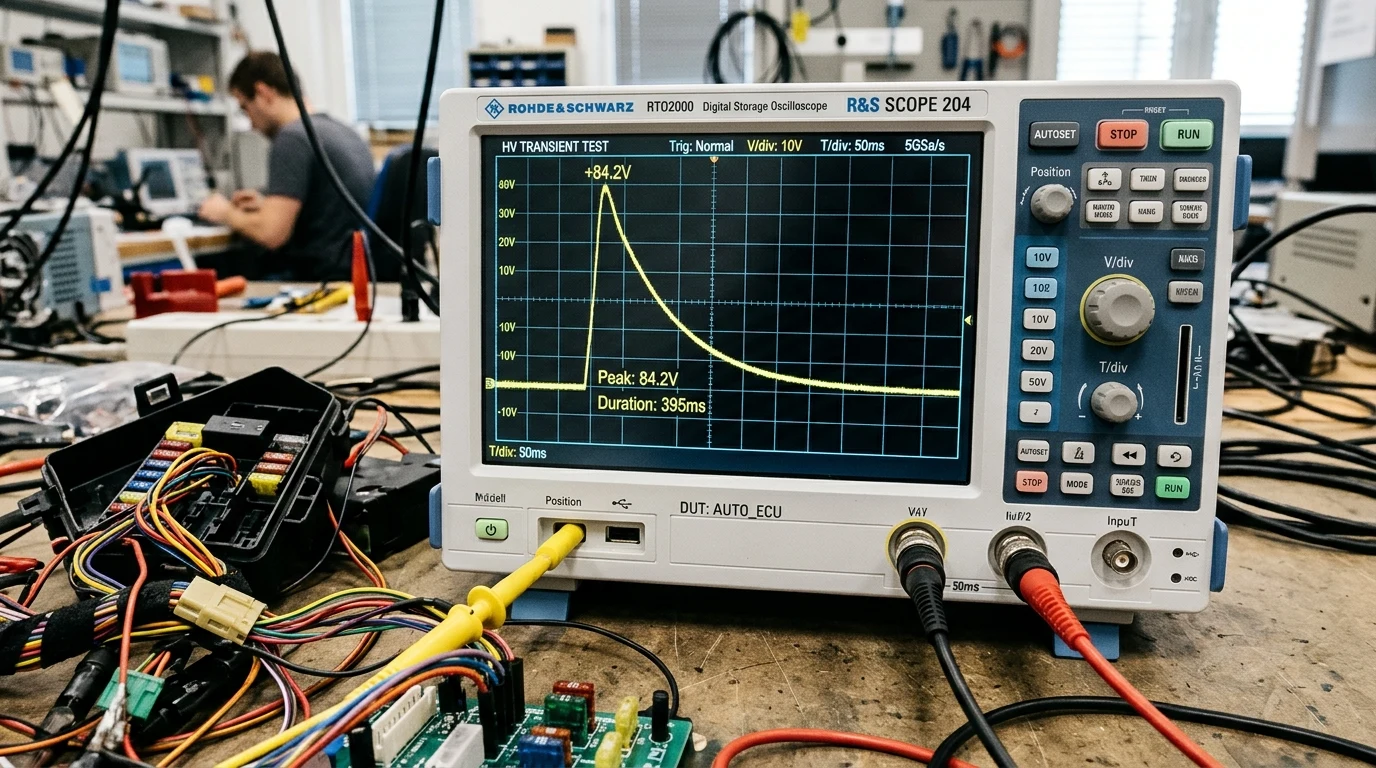
The most catastrophic hazard of direct relay alternator charging is an Automotive Load Dump Transient.
During daylight driving, while an alternator is actively pumping eighty to one hundred amperes into a depleted lithium battery, the internal battery cells gradually approach their upper absorption threshold (three point six five volts per cell). If an individual cell drifts slightly higher than its partners, the Battery Management System (BMS) internal protection logic triggers an instantaneous High Voltage Disconnect (HVD), slamming its solid-state MOSFET switches shut within hundreds of microseconds:
+------------------------------------------------------------------------------------+
|               THE LOAD DUMP TRANSIENT: INDUCTIVE SURGE MECHANISM                   |
+------------------------------------------------------------------------------------+
|                                                                                    |
|  [ Heavy-Duty Alternator ] === 100A DC Current ===> [ LiFePO4 Battery Pack ]        |
|  (Massive Stator Inductance)                        (BMS Suddenly Opens Contacts!) |
|                                                                                    |
|  RESULT: Stator magnetic field collapses instantly across opened circuit.          |
|  V_spike = -L * (dI / dt)  =====> Generates +80V to +120V Inductive Blast!         |
|                                                                                    |
|  CASUALTIES:                                                                       |
|  - Alternator Rectifier Zener Diodes short-circuit.                                |
|  - Vehicle Engine ECU / Transmission Computers fried.                              |
|  - In-cab Touchscreen and Audio Dashboards permanently destroyed.                  |
+------------------------------------------------------------------------------------+
According to ISO Standard 7637-2 (Test Pulse 5a), an unsuppressed load dump generates a high-energy positive voltage spike reaching eighty to one hundred and twenty volts that persists for up to four hundred milliseconds (). This massive inductive energy surge blows through automotive zener diodes and incinerates expensive vehicle powertrain control modules.
Mechanical Solenoid Relays vs Solid-State Buck-Boost Regulators
Resolving these thermodynamic and electrical hazards requires understanding the physical divergence between legacy mechanical switching and modern solid-state power electronics.
Voltage Sensitive Relays and Microcontroller Threshold Hunting
For decades, off-grid builders utilized Voltage Sensitive Relays (VSRs) or Automatic Charging Relays (ACRs) to isolate auxiliary batteries. A VSR operates via a simple analog comparator circuit: when starter battery voltage rises above thirteen point three volts (indicating engine operation), an internal magnetic coil energizes, pulling high-copper contact points together. When voltage falls below twelve point eight volts, the spring forces the contacts apart.
While functional for high-resistance lead-acid systems, VSRs fail completely on LiFePO4 battery banks:
- Relay Chattering and Rapid Cycling: When the VSR closes, the low-impedance lithium battery draws an immediate, brutal current inrush. This sudden massive current draw causes instantaneous voltage sag across the vehicle starter battery and alternator leads (). The voltage dips below the twelve point eight volt release threshold, opening the relay. Once opened, the load vanishes, voltage snaps back above thirteen point three volts, and the relay slams closed again. This rapid chattering cycles multiple times per second, rapidly pitting and welding the mechanical relay contacts.
- Failure to Charge Under Smart Alternators: Because smart alternators routinely cruise at twelve point four to thirteen point zero volts, a VSR never detects its thirteen point three volt threshold, stranding the overland traveler with zero auxiliary charge after ten hours of continuous driving.
Buck-Boost Converters and Programmable Current-Limiting Stages
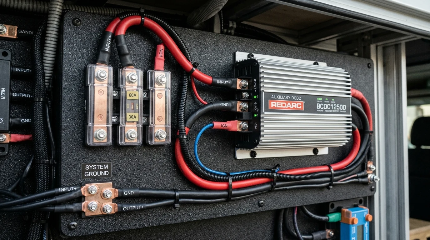
The modern engineering standard for vehicle lithium charging is an active DC-to-DC Battery Charger (such as the Victron Orion-Tr Smart / Orion-XS, Redarc BCDC, or Mastervolt Mac Plus).
A DC-to-DC charger is an advanced high-frequency, microprocessor-controlled buck-boost switching regulator that completely galvanically and electronically isolates the vehicle alternator from the auxiliary lithium storage bank.
+------------------------------------------------------------------------------------+
|               ACTIVE BUCK-BOOST DC-TO-DC CHARGER TOPOLOGY                          |
+------------------------------------------------------------------------------------+
|                                                                                    |
|  [ Vehicle Starter Battery ]                                                       |
|  (Variable: 11.8V to 15.4V)                                                        |
|         |                                                                          |
|         v                                                                          |
|  [ DC-to-DC Charger Input Stage ]                                                  |
|  - Digital Closed-Loop Current Limiter (Limits Draw to 30A / 50A Max)              |
|  - Soft-Start Ramp Controller (Prevents Inrush Voltage Sag)                        |
|         |                                                                          |
|         v                                                                          |
|  [ Synchronous Buck-Boost High-Frequency DC Stage ]                                |
|  - Steps voltage UP or DOWN independently of input swing.                          |
|         |                                                                          |
|         v                                                                          |
|  [ Microprocessor 3-Stage Charging Logic ]                                         |
|  - Precision Bulk (Constant Current)                                               |
|  - Precision Absorption: 14.2V to 14.4V (Constant Voltage)                         |
|  - Precision Float: 13.5V to 13.6V                                                 |
|         |                                                                          |
|         v                                                                          |
|  [ Protected Auxiliary LiFePO4 Battery Bank ]                                      |
|                                                                                    |
+------------------------------------------------------------------------------------+
A buck-boost DC-to-DC charger delivers four definitive engineering advantages:
- Active Stator Current Limiting: Regardless of how depleted the auxiliary lithium battery is, a thirty-ampere DC-to-DC charger draws strictly thirty-five to thirty-eight amperes from the vehicle alternator. The alternator is never driven into current saturation or thermal overload.
- Universal Smart Alternator Compatibility: The internal buck-boost converter operates seamlessly across an ultra-wide input voltage envelope (typically ten to seventeen volts DC). Even if the vehicle ECU drops voltage to twelve point two volts, the charger boosts the output voltage up to fourteen point four volts to charge the lithium cells efficiently.
- Absolute Load Dump Immunity: If the auxiliary lithium BMS trips offline, the DC-to-DC charger’s internal input capacitors and smoothing chokes absorb the small local transient without dropping load on the alternator primary busbar. The vehicle alternator continues powering the vehicle chassis, preventing high-voltage load dump generation entirely.
- Thermal Foldback Protection: High-end DC-to-DC chargers incorporate internal thermistors on their power MOSFET heatsinks. If the vehicle engine bay or equipment cabinet reaches extreme ambient temperatures (sixty degrees Celsius), the charger automatically derates output current from fifty amperes down to twenty-five amperes to prevent electronic failure.
System Integration and Control: Ignition Triggers and Dual Battery Isolation
Properly installing a DC-to-DC charging system requires calibrated control wiring to guarantee that auxiliary charging occurs strictly when the vehicle engine is actively running.
Engine Run Detection via Vibration and Virtual D-Plus Telemetry
Historically, auxiliary relays were triggered by tapping directly into the alternator “D+” (Dynamo Positive) terminal—a dedicated physical wire that went high (twelve volts) only when the alternator stator was spinning.
In modern computerized vehicles, the physical D+ wire has been replaced by multiplexed CAN-bus and LIN-bus digital networks. Modern DC-to-DC chargers overcome this through two distinct integration methodologies:
+------------------------------------------------------------------------------------+
|               DC-TO-DC CHARGER ENGINE RUN DETECTION PROTOCOLS                      |
+------------------------------------------------------------------------------------+
|  METHODOLOGY           CONTROL LOGIC                       WIRING REQUIREMENTS     |
+------------------------------------------------------------------------------------+
|  Hardwired Ignition    Ties to vehicle "Key-On Engine Run" Single 18 AWG trigger   |
|  Terminal (D+)         fuse in main vehicle fuse box.      wire routed through     |
|                        Engages only when ignition is activefirewall conduit.       |
|                                                                                    |
|  Smart Voltage &       DSP monitors starter battery voltageZero control wires;     |
|  Vibration Sensing     patterns, detecting alternator AC   operates entirely across|
|  (Virtual D+)          rectifier ripple and engine pulses. heavy DC input cables.  |
+------------------------------------------------------------------------------------+
Advanced units (such as the Victron Orion series) utilize programmable software voltage windows:
- Engine Run Voltage Detection Threshold (): Set to thirteen point four volts for standard alternators, or twelve point eight volts for smart alternators.
- Engine Shutdown Detection Threshold (): Set to twelve point four volts with a thirty-second delay timer.
When the vehicle engine stops, the starter battery voltage decays below twelve point four volts. The internal microprocessor shuts down the buck-boost conversion stage, dropping standby parasitic current below one milliampere () and completely eliminating starter battery drain.
Starter Battery Preservation and Reverse Charging Float Modes
An emerging feature in premium expedition vehicle power systems is Bidirectional Reverse Trickle Charging.
During long periods of off-grid campsite parking, the vehicle engine sits dark while rooftop solar panels generate surplus electrical power. While the primary solar charge controller replenishes the auxiliary LiFePO4 bank to one hundred percent state of charge, the vehicle’s starting battery slowly drains due to parasitic vehicle anti-theft alarms, GPS trackers, and keyless entry radio modules.
Advanced DC-to-DC chargers (such as the Redarc BCDC Core and Mastervolt series) feature automatic reverse trickle charging: once the auxiliary lithium battery reaches ninety-five percent capacity via rooftop solar, the charger routes a current-limited float trickle (typically two to three amperes at thirteen point six volts) backward into the vehicle starter battery, ensuring the engine cranks instantaneously even after six weeks of remote off-grid boondocking.
Complete Alternator Charging Commissioning and Protection Protocol
When commissioning an auxiliary lithium alternator charging system on a truck, van, or marine vessel, certified electrical technicians follow this rigorous commissioning protocol:
+------------------------------------------------------------------------------------+
|             ENGINEERING COMMISSIONING CHECKLIST: ALTERNATOR CHARGING               |
+------------------------------------------------------------------------------------+
|  STEP  PHASE               ACTION ITEM                         SPECIFICATION       |
+------------------------------------------------------------------------------------+
|  01    Conductor Sizing    Calculate Full-Loop Voltage Drop    Under 2.5% Drop     |
|                            Size primary DC conductors between  At full charger amp |
|                            starter battery and DC-DC unit      draw (e.g. 4 AWG for|
|                            accounting for total circuit length.30A at 15 feet).    |
|                                                                                    |
|  02    Overcurrent Fusing  Install Dual MIDI / Mega Fuses      60A Fuse for 30A Unit|
|                            Place high-grade fuse within 12 in  Install at BOTH     |
|                            of starter battery positive AND     starter battery and |
|                            auxiliary lithium positive stud.    lithium bank sides. |
|                                                                                    |
|  03    Chassis Grounding   Verify Common Earth Reference       Star Grounding Stud |
|                            Ensure negative input routes to     Direct to chassis   |
|                            heavy chassis unpainted factory     ground lug (under   |
|                            ground bolt or battery negative.    0.05 Ω resistance). |
|                                                                                    |
|  04    Engine Run Lockout  Calibrate Shutdown Voltage Envelope Smart Alternator    |
|                            Program start threshold to 13.0V    Shutdown at 12.3V   |
|                            and shutdown threshold to 12.4V     after 60-second     |
|                            with appropriate delayed lockout.   engine-off delay.   |
|                                                                                    |
|  05    Thermal Run Test    Thirty-Minute Full-Load Idle Audit  Stator Thermal Scan |
|                            Run engine at low idle (650 RPM)    Alternator casing   |
|                            with depleted lithium bank; audit   must stabilize      |
|                            alternator casing with IR camera.   under 115°C max.    |
|                                                                                    |
|  06    Full Cutoff Safety  Test Abrupt BMS Isolation           Zero Load Dump Spike|
|                            Manually disconnect lithium breaker Confirm voltage on  |
|                            during full alternator charging;    starter busbar stays|
|                            audit starter busbar with scope.    safely under 16.0V. |
+------------------------------------------------------------------------------------+
By ditching primitive mechanical solenoid relays in favor of micro-controlled buck-boost DC-to-DC converters, mobile solar engineers safeguard expensive vehicle alternators, guarantee predictable lithium charging across all driving cycles, and eliminate the catastrophic electrical transients that jeopardize modern overland expeditions.