Industrial metalworking and woodworking machinery represents the pinnacle of mechanical durability. Heavy cast-iron equipment—such as vintage Bridgeport vertical milling machines, Clausing metal lathes, industrial wide-belt sanders, and commercial cabinet table saws—is overwhelmingly engineered to operate on three-phase alternating current.
In suburban industrial parks, three-phase commercial utility service is standard. In remote off-grid locations, homesteaders and rural fabricators generate power through residential split-phase solar inverters (such as an EG4 18KPV, Sol-Ark 15K, or Schneider Conext XW Pro) that deliver exclusively 120V/240V single-phase power.
Attempting to run commercial three-phase machinery from single-phase solar storage requires artificial phase generation. Homesteaders face a fundamental engineering fork in the road: do you install an electromechanical Rotary Phase Converter (RPC) to manufacture a traditional three-phase power grid for your entire workshop, or do you retrofit your equipment with solid-state Variable Frequency Drives (VFDs)?
While both technologies bridge the single-phase to three-phase gap, their electrical behaviors on an off-grid solar and battery system are radically opposed. An RPC introduces brutal idle standby battery losses and massive inductive motor starting surges, while a VFD provides silky-smooth zero-inrush acceleration but injects high-frequency electrical harmonics that can disrupt sensitive pure sine wave inverters.
This engineering comparison benchmarks the mechanical and electrical trade-offs between Rotary Phase Converters and Variable Frequency Drives, analyzing starting surges, idle tare power consumption, wild-leg voltage hazards, and inverter compatibility.
Executive Summary: The Three-Phase Dilemma in Off-Grid Workshops
Three-phase alternating current delivers electrical power through three separate sinusoidal voltage conductors, each offset by one hundred and twenty electrical degrees ( phase angle shift):
+-----------------------------------------------------------------------------------+
|               SINGLE-PHASE SPLIT-PHASE VS THREE-PHASE POWER PHASING               |
+-----------------------------------------------------------------------------------+
|  SINGLE-PHASE (Residential Solar Inverter):                                       |
|  Line 1 (0°) -----------------\                                                   |
|  Line 2 (180°) ----------------+---> Net 240V RMS (Pulsating Mechanical Torque)   |
|                                                                                   |
|  THREE-PHASE (Industrial Utility / Machine Tools):                                |
|  Phase A (0°)   ----\                                                             |
|  Phase B (120°) -----+---> Smooth, Continuous 360° Rotating Magnetic Field        |
|  Phase C (240°) ----/      Instant Directional Reversal, 150% Power Density       |
+-----------------------------------------------------------------------------------+
When single-phase solar power enters a workshop, builders must evaluate two contrasting conversion architectures:
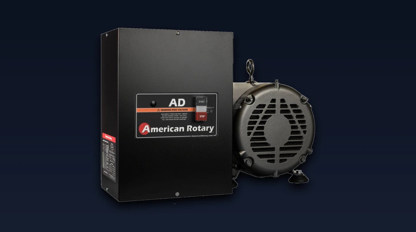
- Rotary Phase Converter (American Rotary AR15): Uses an oversized, heavily balanced rotary idler motor. Two legs of incoming 240V solar power pass straight through to the load, while the spinning idler acts as a rotary induction generator to manufacture the missing third phase.
- Core Off-Grid Trade-off: High mechanical ruggedness and multi-machine versatility, countered by 400W to 800W of continuous idling battery drain and severe starting surge requirements.
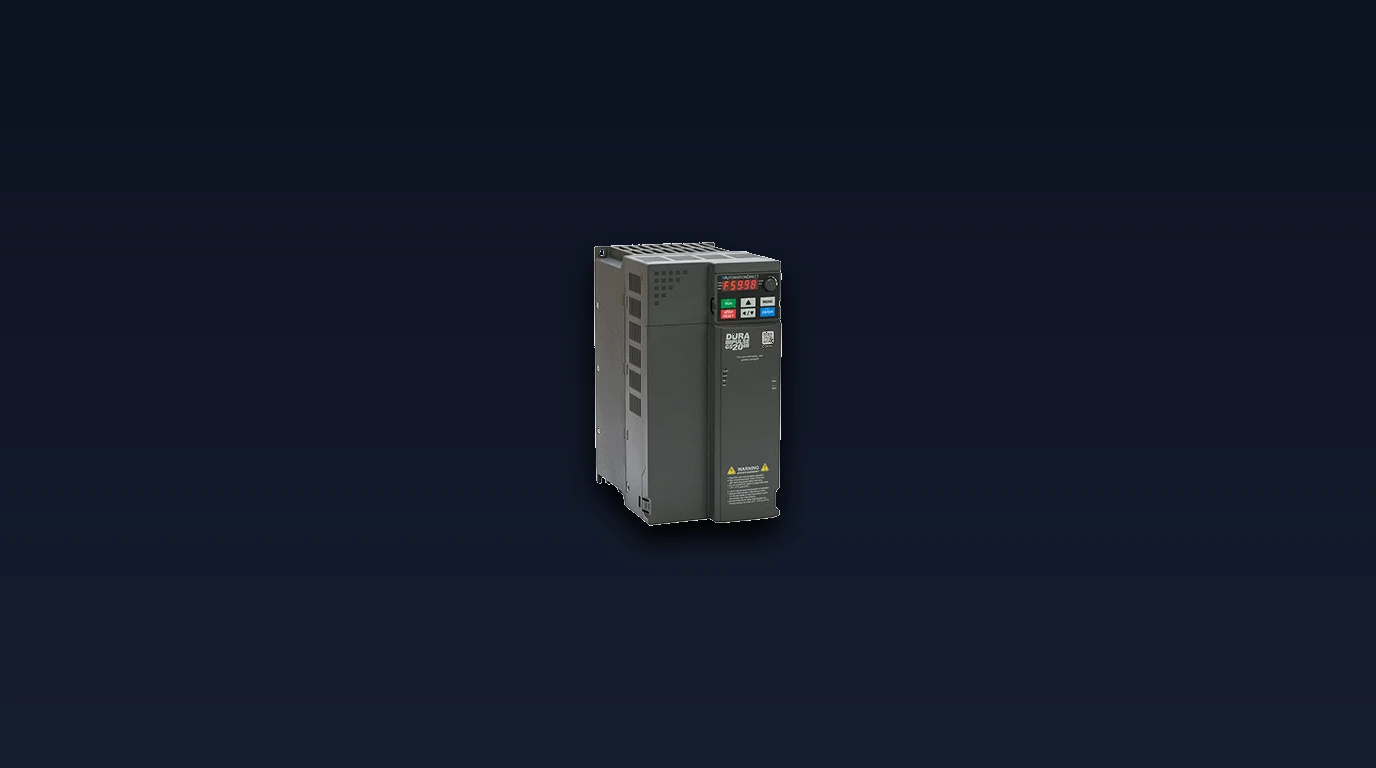
- Variable Frequency Drive (AutomationDirect GS20): Takes single-phase 240V AC power, rectifies it into a high-voltage direct-current bus, and uses Insulated Gate Bipolar Transistors (IGBTs) to synthesize pure three-phase power at any desired frequency.
- Core Off-Grid Trade-off: Zero starting surge and virtually zero idle tare loss, countered by the limitation of dedicating one VFD to one motor and potential harmonic feedback into the solar inverter.
Physics of Polyphase Power: Why Industrial Machinery Requires Three Phases
To understand why heavy workshop equipment utilizes three-phase power rather than standard single-phase power, engineers examine motor rotor dynamics.
The Rotating Magnetic Field and Constant Mechanical Torque
In a single-phase induction motor, line voltage oscillates back and forth across a single axis. The magnetic field expands and collapses, but it does not naturally rotate. To initiate rotation, single-phase motors require auxiliary start windings, centrifugal mechanical switches, and start capacitors. Furthermore, electrical power drops to zero volts twice per cycle, causing pulsating torque, vibration, and lower mechanical efficiency.
In a three-phase motor, the three sets of stator coils energized at one-hundred-and-twenty-degree phase offsets generate a smooth, continuous rotating magnetic field (RMF):
- Constant Mechanical Torque: Instantaneous power delivered to a balanced three-phase load is completely constant at all fractions of a second (). Industrial cutters on lathes and mills produce flawless surface finishes because the spindle never experiences torque pulsation.
- Zero Centrifugal Switches: Three-phase motors contain zero mechanical centrifugal switches, start capacitors, or contact points. They are virtually indestructible, capable of running continuously for decades in dusty shop environments.
The High-Leg Delta Geometry and Wild Leg Voltage Hazards
When a Rotary Phase Converter manufactures the third leg from single-phase split-phase power, it establishes a High-Leg Delta configuration:
+-----------------------------------------------------------------------------------+
|                        HIGH-LEG DELTA VOLTAGE TOPOLOGY                            |
+-----------------------------------------------------------------------------------+
|                                                                                   |
|                   Phase A (120V to Neutral)                                       |
|                         /\                                                        |
|                        /  \                                                       |
|       240V Line-Line  /    \  240V Line-Line                                      |
|                      /      \                                                     |
|                     /        \                                                    |
|  Phase B ----------+---------- Phase C [ Manufactured "Wild Leg" ]                |
|  (120V to Neutral)       |             (208V to Neutral!)                         |
|                          v                                                        |
|                       Neutral                                                     |
|                                                                                   |
|  DANGER: Tapping Phase C to Neutral for 120V coils DESTROYS control circuitry!    |
+-----------------------------------------------------------------------------------+- Line-to-Line Voltages: Between any two phase lines (A-B, B-C, C-A), voltage measures a nominal 240V AC, providing full balanced power across the motor windings.
- Line-to-Neutral Voltages: Phase A to Neutral is 120V. Phase B to Neutral is 120V. However, Phase C (the manufactured wild leg) measures approximately 208V to Neutral:
[!CAUTION] If a machine tool contains a 120V magnetic starter coil, digital readout (DRO), or work lamp wired between incoming line power and neutral, connecting the manufactured wild leg to that circuit will instantly subject the 120V electronics to 208V, causing immediate dielectric burnout!
Rotary Phase Converters: Electromechanical Grid Generation
The Rotary Phase Converter is the traditional, heavy-duty solution for running multiple machines from a single power source.
The Idler Motor Induction Architecture
An RPC consists of two primary components: an electrical control enclosure containing heavy motor-start capacitors, run-balancing capacitors, and potential relays, paired with a custom-wound rotary idler motor:
- Starting the Idler: The control box energizes large start capacitors to spin up the unloaded idler motor from single-phase 240V power. Once the idler reaches operating speed (typically 1,750 or 3,500 RPM), a potential relay disconnects the start capacitors.
- Induction Generation: The idler’s rotor continues spinning on its low-friction bearings. As the single-phase magnetic field sweeps across the spinning rotor bars, it induces currents that generate a secondary magnetic flux.
- Third Leg Induction: This internal rotating magnetic field cuts across the third winding in the stator, generating an authentic third sinusoidal AC voltage waveform.
+-----------------------------------------------------------------------------------+
|                       ROTARY PHASE CONVERTER POWER FLOW                           |
+-----------------------------------------------------------------------------------+
|  [ Solar Inverter 240V ]                                                          |
|       |                                                                           |
|       +==================== Phase A ====================> [ Shop 3-Phase Panel ]  |
|       |                                                                           |
|       +==================== Phase B ====================> [ Shop 3-Phase Panel ]  |
|       |                                                           ^               |
|       v                                                           |               |
|  [ RPC Control Box ] ===> [ Rotary Idler Motor ] === Phase C =====+ (Wild Leg)    |
|   (Capacitor Bank)          (Generates 3rd Leg)                                   |
+-----------------------------------------------------------------------------------+
Operational Strengths: Multi-Tool Operation and Voltage Balancing
- Powers Entire Distribution Panels: An RPC feeds directly into a standard three-phase breaker panel. Once running, you can operate a table saw, bandsaw, dust collector, and milling machine simultaneously, exactly like utility three-phase power.
- Impervious to Complex Machine Controls: Equipment with multi-speed windings, two-speed gearboxes, forward/reverse drum switches, automatic power feeds, and CNC computers operate without modification.
- Enormous Overload Headroom: The heavy spinning mass of the idler rotor acts as a mechanical flywheel, absorbing heavy motor starting spikes without dropping voltage.
The Severe Off-Grid Penalties: Idle Tare Loss and Starting Surges
For an off-grid solar installation, an RPC presents two massive electrical handicaps:
- Continuous Idling Battery Drain: Even when every tool in your shop is turned off, an energized ten-horsepower idler motor draws between 400W and 750W of continuous idling tare power:
Leaving an RPC running throughout an eight-hour workday consumes nearly five kilowatt-hours of battery capacity purely to spin the idler in circles. 2. Idler Starting Inrush Surge: Starting a ten-horsepower RPC idler motor draws a momentary across-the-line surge of 80 to 120 Amps. An off-grid solar inverter must be oversized (minimum 12kW to 15kW continuous output) simply to start the idler motor without tripping into overcurrent fault.
Variable Frequency Drives: Solid-State Inversion and Digital Modulation
Variable Frequency Drives represent modern semiconductor power electronics applied directly to individual machine tools.
Rectification, DC Bus Filtering, and Pulse-Width Inversion
A VFD operates on a three-stage solid-state conversion topology:
- Full-Wave Diode Rectification: Incoming single-phase 240V AC power enters a heavy diode bridge, converting AC into raw pulsating direct current.
- DC Link Bus Capacitor Bank: A bank of high-voltage electrolytic capacitors smooths the rectified voltage into a stable, ripple-free direct-current bus measuring approximately:
- IGBT Inverter Bridge: Six Insulated Gate Bipolar Transistors (IGBTs) rapidly switch the DC bus voltage on and off at carrier frequencies between four and sixteen kilohertz (kHz). By modulating the pulse width (PWM), the microprocessor synthesizes perfectly balanced, clean three-phase sinusoidal currents into the motor windings.
+-----------------------------------------------------------------------------------+
|                        VFD SOLID-STATE CONVERSION TOPOLOGY                        |
+-----------------------------------------------------------------------------------+
|  [ Single-Phase 240V AC ]                                                         |
|             |                                                                     |
|             v                                                                     |
|  [ Diode Bridge Rectifier ] ===> Converts to pulsating DC                         |
|             |                                                                     |
|             v                                                                     |
|  [ 340V DC Capacitor Bus ]  ===> Smooths direct current energy reservoir          |
|             |                                                                     |
|             v                                                                     |
|  [ Microprocessor IGBTs ]   ===> Pulse Width Modulation (0 to 400 Hz)             |
|             |                                                                     |
|             v                                                                     |
|  [ Three-Phase Motor ]      ===> Perfect 120° Balanced Waveforms, Smooth Torque   |
+-----------------------------------------------------------------------------------+
The Off-Grid Savior: Pure Zero-Inrush Soft Starting
The paramount advantage of a VFD in an off-grid solar system is complete elimination of startup inrush current:
- Programmable Acceleration Ramps: Instead of slamming a stationary three-horsepower motor across the line (which demands 45 Amps LRA), the VFD initiates rotation at one Hertz and ramps frequency smoothly up to sixty Hertz over two to five seconds.
- Peak Current Never Exceeds Full Load Amps: Starting current never exceeds the motor’s nominal running current ().
- Zero Inverter Stress: A standard 6,000-watt off-grid inverter (such as an EG4 6000XP) can easily start a five-horsepower milling machine or heavy metal lathe without the slightest voltage sag or light flicker.
- Near-Zero Idle Consumption: When the machine is idle, a VFD consumes only 10W to 20W to power its display and cooling fan—saving ninety-five percent of the idle battery power wasted by an RPC.
Operational Limitations: Single-Motor Topology and Harmonic Injection
- Dedicated One-to-One Coupling: A standard VFD must be wired directly to a single motor. You cannot install a single VFD ahead of a workshop panel to run multiple tools.
- Interlocks and Control Isolation: The VFD must control the motor directly. Opening a mechanical magnetic switch or drum switch between the VFD output and the motor while running will instantly destroy the VFD’s output transistors.
- High-Frequency Harmonics: Fast IGBT switching generates electrical noise and high total harmonic distortion (THD) that can feed back into solar inverters.
Solar Inverter Sizing and Harmonic Filtering Strategies
When operating high-power inductive or non-linear loads from off-grid split-phase inverters, electrical engineers must mitigate two specific failure mechanisms:
+-----------------------------------------------------------------------------------+
|                   ELECTRICAL NOISE MITIGATION TOPOLOGIES                          |
+-----------------------------------------------------------------------------------+
|  [ Solar Inverter ] ===> [ Line Reactor (3% Impedance) ] ===> [ VFD ]             |
|                                                                 |                 |
|  BENEFIT: Suppresses harmonic current spikes;                   v                 |
|           Protects inverter bridge from non-linear ringing.  [ Motor ]            |
+-----------------------------------------------------------------------------------+
Mitigating Total Harmonic Distortion on Pure Sine Wave Inverters
Because standard VFDs draw power through non-linear diode rectifiers, current is pulled in brief, high-magnitude pulses at the peaks of the voltage wave. This non-sinusoidal current draw causes voltage waveform clipping, increasing Total Harmonic Distortion (THD).
- In an off-grid inverter with high output impedance, unchecked VFD harmonics can distort the 240V AC output waveform, triggering inverter error codes, overheating sensitive power supplies, or disrupting induction cooktops elsewhere in the home.
- The Solution: 3% Input Line Reactors: Installing an inexpensive three-percent impedance AC line reactor between the solar inverter output and the VFD input smooths current crests, reduces harmonic distortion below five percent, and shields the VFD from transient voltage spikes.
Side-by-Side Engineering Matrix and Final Selection Guide
To assist off-grid fabricators and homestead machinists in selecting the ideal phase-conversion strategy, consult this definitive engineering comparison matrix:
| Technical Feature | American Rotary AR15 Rotary Phase Converter | AutomationDirect GS20 Variable Frequency Drive |
|---|---|---|
| Operating Technology | Electromechanical Induction Idler Motor | IGBT Solid-State Pulse-Width Modulation |
| Startup Inrush Surge | Severe (80A to 120A Inrush) | Zero (Controlled soft ramp from 0A) |
| Continuous Idle Power | 450W to 750W (Heavy battery drain) | 12W to 18W (Negligible battery draw) |
| Minimum Solar Inverter | 12kW to 15kW Continuous Output | 5kW to 6kW Continuous Output |
| Multi-Machine Capability | Yes (Powers whole workshop panel) | No (Dedicated one VFD per motor) |
| Speed Control & Braking | Fixed 60 Hz Speed / Mechanical brake | Fully Variable Speed / Dynamic DC braking |
| Voltage Balance | 2% to 4% (With manufactured wild leg) | 100% Balanced Virtual Three-Phase |
| Harmonic Distortion | Zero (Pure linear inductive load) | Moderate (Requires 3% Line Reactor) |
| Mechanical Maintenance | Grease bearings every 10,000 hours | 100% Solid-State (Blow out dust filters) |
+-----------------------------------------------------------------------------------+
|                        SELECTION DECISION FLOWCHART                               |
+-----------------------------------------------------------------------------------+
|  Are you running an entire shop with multi-motor machines & complex 120V controls?|
|  ├── YES: Choose Rotary Phase Converter (American Rotary AR15)                    |
|  │        Requirements: 12kW+ inverter, 30kWh+ battery bank, strict panel labels. |
|  │                                                                                |
|  └── NO (Single heavy tools: Bridgeport mill, metal lathe, bandsaw, table saw):   |
|           Choose Variable Frequency Drive (AutomationDirect GS20)                 |
|           Benefits: Zero inrush, runs on 6kW inverter, zero idle loss, speed knob.|
+-----------------------------------------------------------------------------------+
Final Engineering Verdict
In an off-grid solar workshop, battery energy conservation and inverter surge headroom are the dominant engineering constraints.
For the vast majority of off-grid homesteaders operating individual machine tools—such as a vertical milling machine, metal lathe, or heavy drill press—the Variable Frequency Drive (AutomationDirect GS20) is our definitive choice. Its ability to start heavy motors with zero inrush current, provide variable spindle speed control, and consume negligible idle standby power perfectly aligns with off-grid battery limitations.
However, for professional off-grid fabrication businesses operating multi-machine workshops, hydraulic surface grinders, and complex machinery with auxiliary feed motors and power tool changers, the Rotary Phase Converter (American Rotary AR15) remains the undisputed champion for creating an authentic, rugged three-phase industrial grid from clean solar power.